Rockwell Automation Publication 442L-UM005B-EN-P - April 2017 35
Configurable Functions Chapter 3
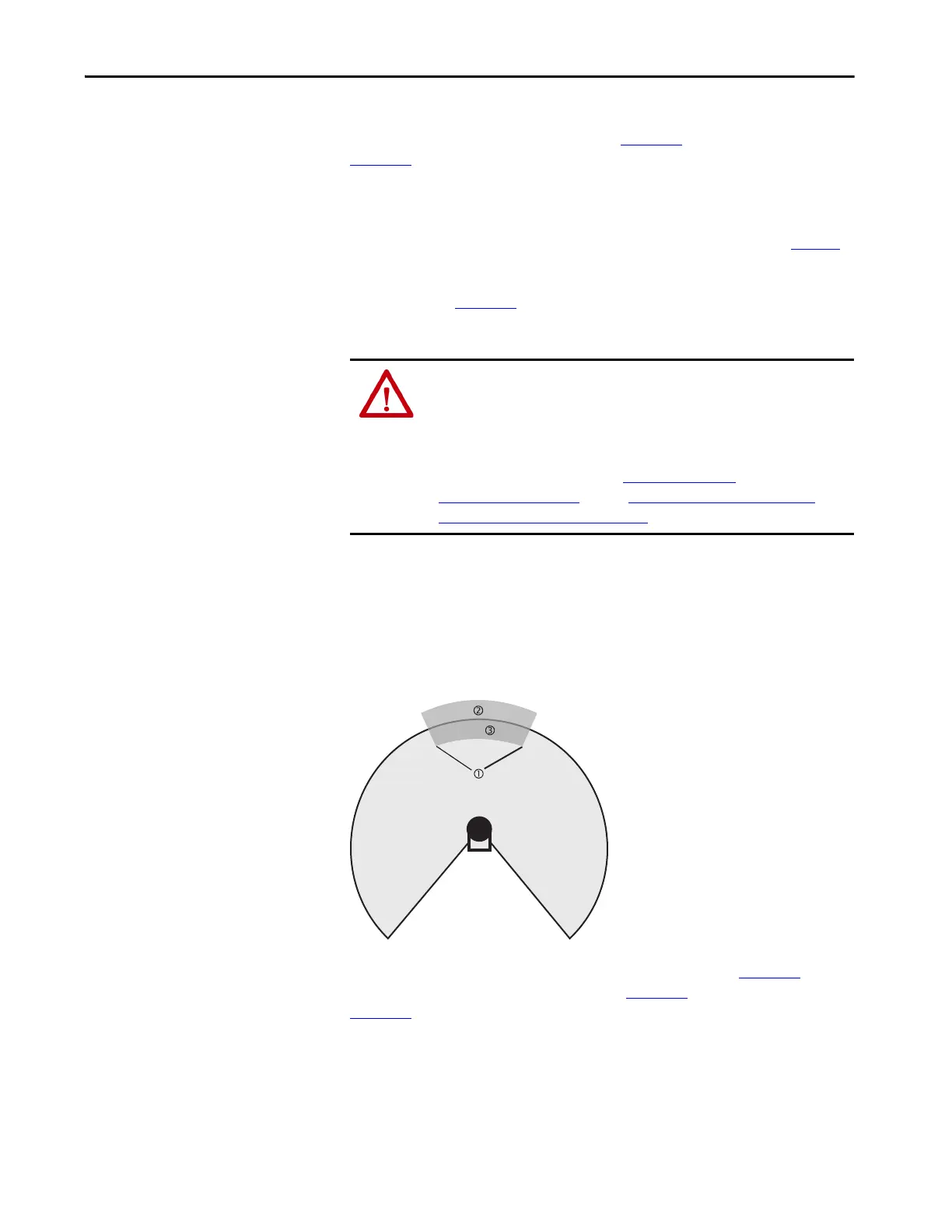
In those places at which the surrounding contour is smaller than the maximum
protective field range (for example, at 1 in Figure 11
), the protective field (4 in
Figure 11
) corresponds to the surrounding contour.
In those places where the surrounding contour is larger than the protective
field range (3 in Figure 11
) the protective field corresponds to the possible
scanning range.
Use the Contour as a Reference
In addition to the protective field, the SafeZone Mini device can also monitor a
contour (for example, the floor in vertical applications).
Figure 12 - Schematic Diagram of Contour as Reference
For contour monitoring, you define a contour segment (1 in Figure 12). The
contour segment comprises a positive (2 in Figure 12
) and a negative (3 in
Figure 12
) tolerance band.
TIP The measuring error tolerances for the SafeZone Mini device are
automatically subtracted from the protective field size. As a result the
protective field is slightly smaller than the surface covered (2 in Figure 11
).
ATTENTION: Check the protective field suggested by the SCD software
The protective field suggested by the SCD software is not a replacement for
the calculation of the minimum distance. Calculate the minimum distance
and check the effectiveness of the protective fields before commissioning the
application.
Pay attention to the descriptions in Mounting on page 39
, the notes in
Commissioning on page 71
, and the Checklist to Install Electro-sensitive
Protective Equipment (ESPE) on page 97.
 Loading...