64 Rockwell Automation Publication 442L-UM005B-EN-P - April 2017
Chapter 5 Electrical Installation
Table 10 - Core Assignment of the SafeZone Mini Device Cable
Universal I/O Connections
Configuration Connection
M8 × 4 (Serial Interface)
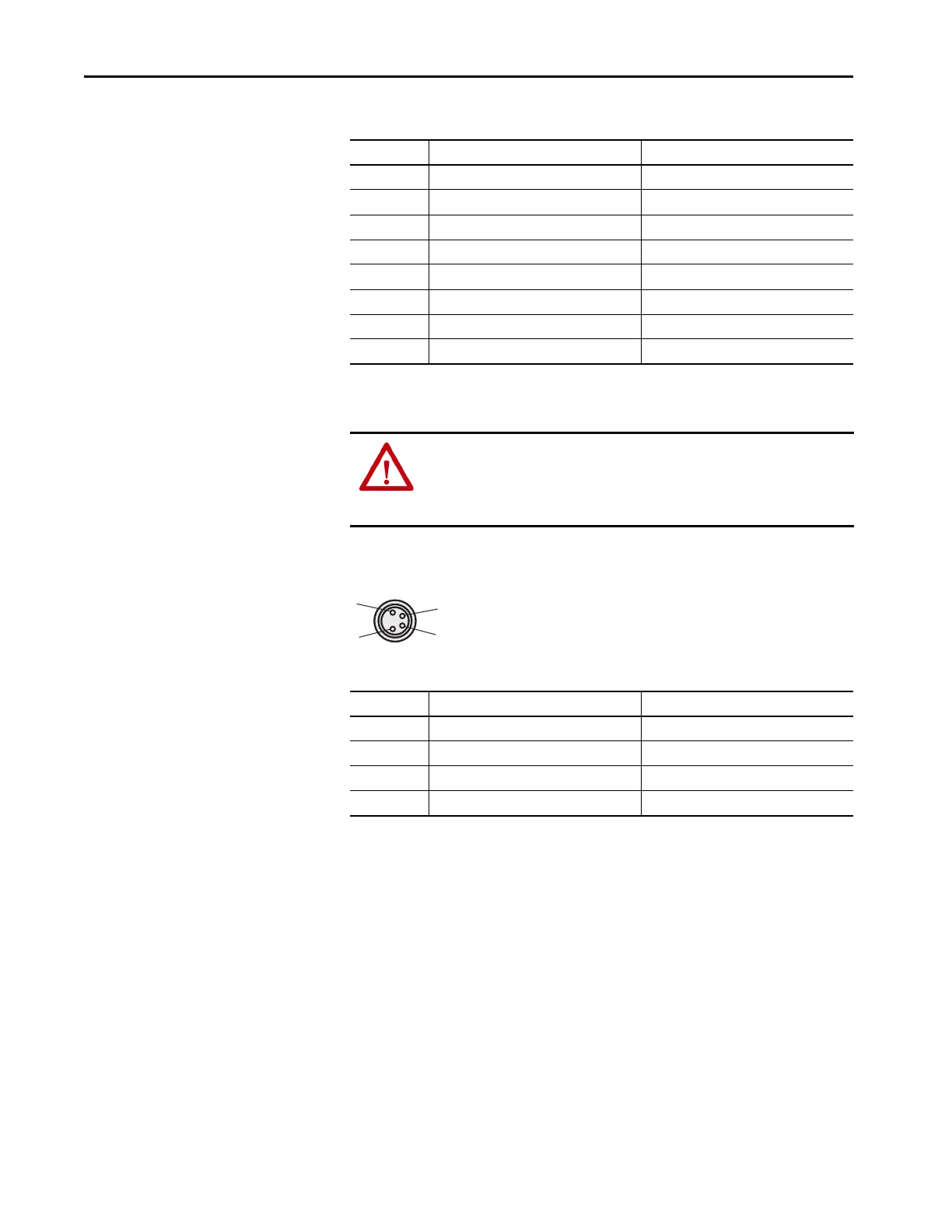
Figure 39 - Pin Assignment
Table 11 - Pin Assignment Configuration Connection M8 × 4
After configuration:
• Always remove the connecting cable from the configuration connection.
• Locate the attached protection cap to cover the configuration
connection.
Core Color Function
1 White Output for warning field 1
2 Brown Supply voltage 24V DC
3 Green Universal I/O connection 1
4 Yellow Universal I/O connection 2
5 Gray Output signal switching device OSSD1
6 Pink Output signal switching device OSSD2
7Blue Supply voltage 0V DC
8 FE/shield Functional earth/shield
ATTENTION: Do not use the universal I/O connection outputs for safety-
related tasks. The universal I/O connection outputs are purely application
diagnostics outputs, for example, for the transfer of information to
controllers.
Pin SafeZone Mini Device PC-side RS-232-D-Sub
1 Reserved Not assigned
2 RxD Pin 3
30V DC (voltage supply) Pin 5
4 TxD Pin 2
 Loading...