62 Rockwell Automation Publication 442L-UM005B-EN-P - April 2017
Chapter 5 Electrical Installation
Electrical Notes
• Route all cables and connection cables such that they are protected from
damage.
• Verify that the controller that is connected and all devices that are
related to safety have the required category as per EN ISO 13849-1 or
the required Performance Level as per EN ISO 13849-1.
• If you use screened cables, lay the screen evenly around the connection
terminal.
• Verify that the SafeZone™ Mini device is adequately protected
electrically. See Electrical Specifications on page 89
for the electrical data
necessary for determining the correct fuse.
System Connection
All inputs and outputs on the SafeZone Mini device are on the round plug
connector on the connecting cable. Connect the SafeZone Mini device with
pre-assembled extension cables (see Table 10 on page 64
).
All inputs and outputs on the SafeZone Mini device are to be used only in the
context specified.
The round plug connectors are coded. If you use plug connectors other than
the connectors intended, any claim against Rockwell Automation under the
warranty is rendered void.
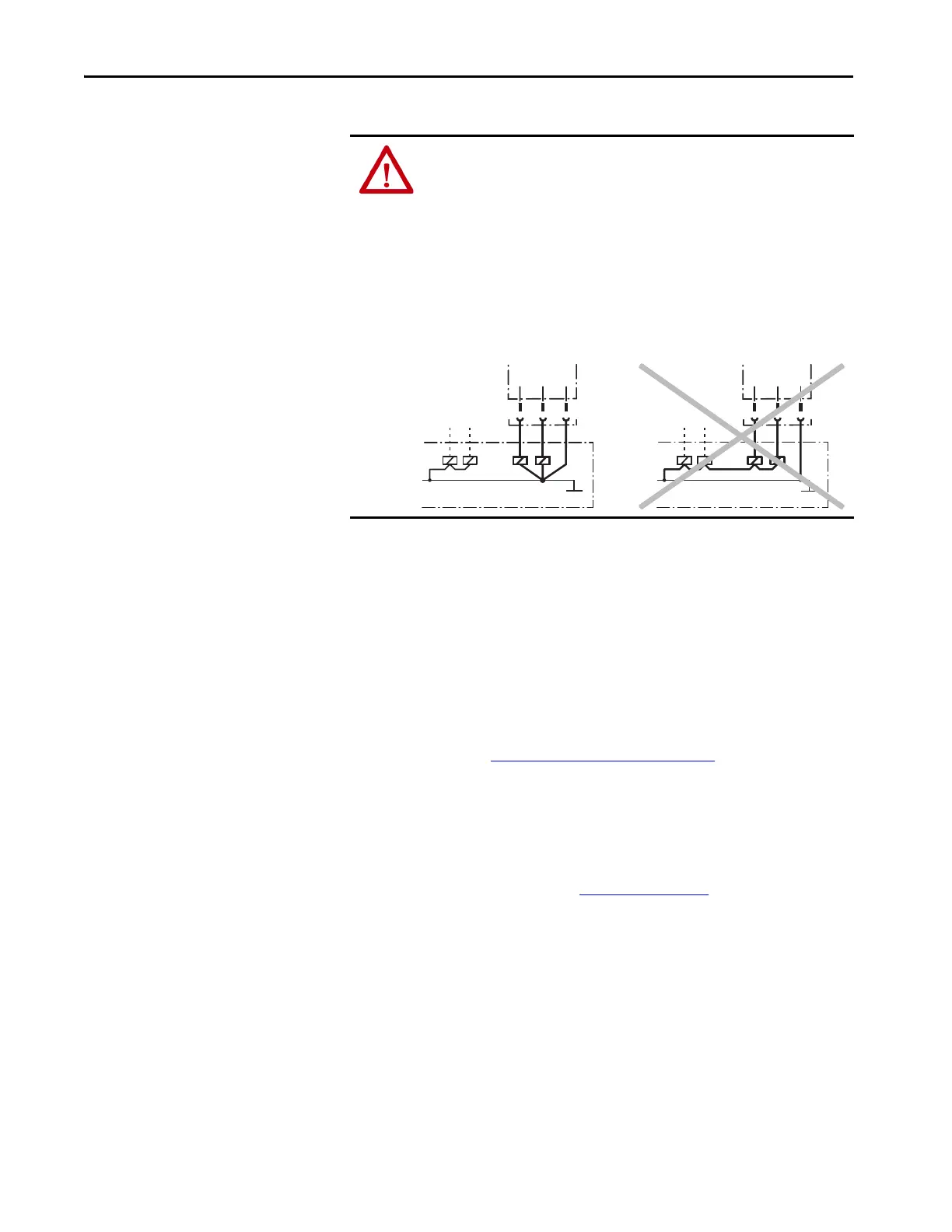
ATTENTION: Help prevent the occurrence of a potential difference between
the load and the protective device.
If you connect loads that are not reverse-polarity protected to the OSSDs or
the safety outputs, you must connect the 0V connections of these loads and
of the corresponding protective device individually and directly to the same
0V terminal strip. This is the only way to verify that, if there is an anomaly,
there is no potential difference between the 0V connections of the loads and
of the corresponding protective device.
OSSD1
OSSD2
Safety output 1
Safety output 2
OSSD1
OSSD2
Safety output 1
Safety output 2
 Loading...