Rockwell Automation Publication 442L-UM005B-EN-P - April 2017 77
Maintenance and Care Chapter 9
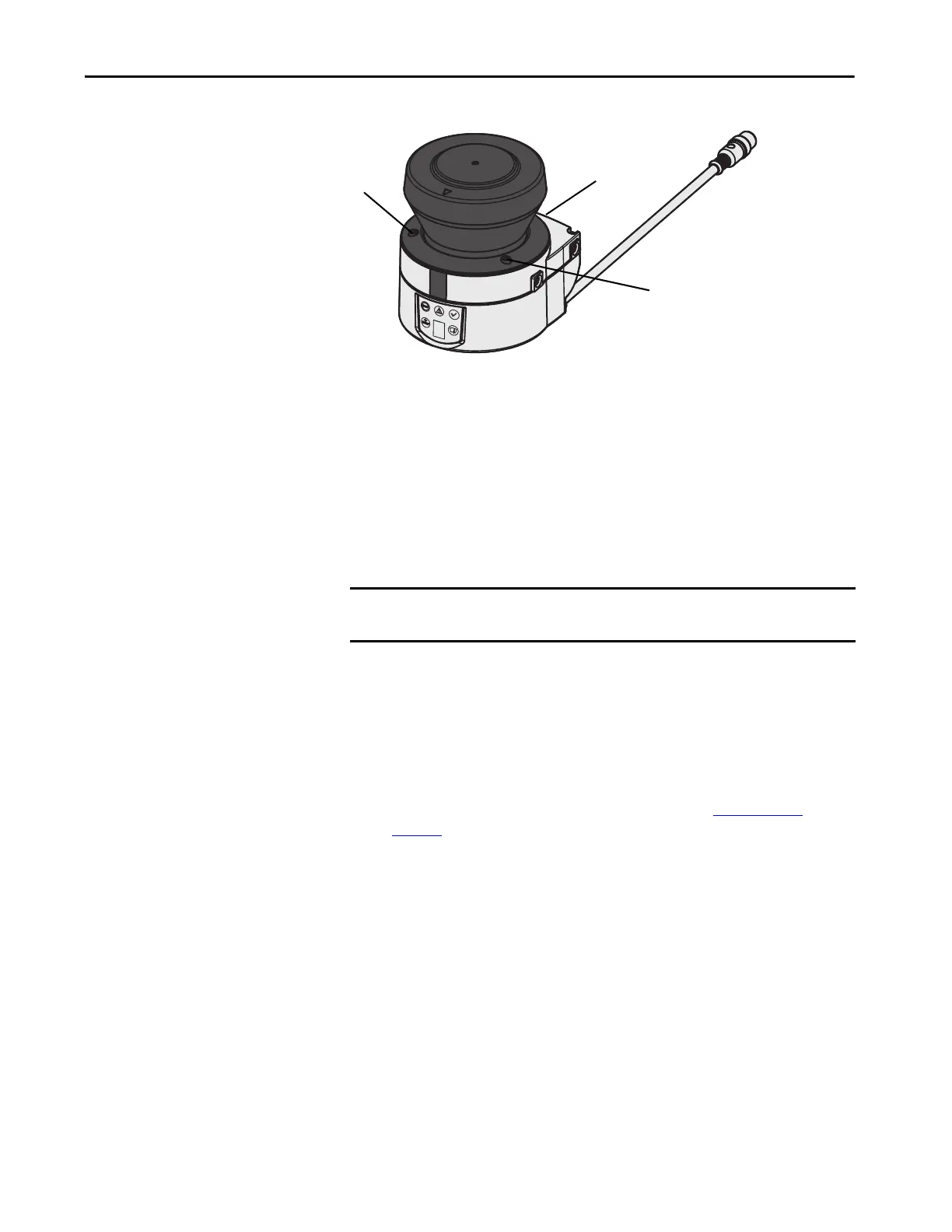
Figure 47 - Optics Cover Mounting Screws
5. Remove the optics cover.
6. Check whether the mirror on the motor is clean and remove any
contamination with an optic brush.
7. Take the new optics cover out of the packaging and remove the
protection for the seal.
8. Remove any remnants of packaging.
9. Place the optics cover on the safety laser scanner and place the new
mounting screws.
10. Tighten the front screws with the torque wrench.
11. Make sure that the optics cover is free of dirt and that it is not damaged.
Recommission the SafeZone Mini Device
1. Correctly remount the SafeZone Mini device (see Mounting on
page 39).
2. Connect the round plug connector on the end of the connection cable
for the SafeZone Mini device.
3. Perform an optics cover calibration with the aid of the SCD software.
IMPORTANT When fitting the new cover, verify that the arrow on the top of the cover
points to the front and that the optics cover is fully in contact without a gap.
 Loading...