Rockwell Automation Publication 442L-UM005B-EN-P - April 2017 81
Diagnostics Chapter 10
Error and Status
Indication —
Seven-segment Display
This section explains the meaning of the error indications on the
seven-segment display and how to respond to the messages. You can find a
description of the positions and symbols on the SafeZone Mini device in Status
Indicators on page 23.
Lockout Operational Status
In case of certain faults or an erroneous configuration, the device can go into
the lockout operational status. The seven-segment display on the safety laser
scanner then indicates
, , , , , , , , , or . To place the device back in
operation, follow these steps:
1. Rectify the cause of the fault per Table 15 on page 81
.
2. Switch off the power supply for the SafeZone Mini device, wait at least 3
seconds, and then switch back on the power supply.
Or, restart the safety laser scanner with the aid of the SCD software.
.
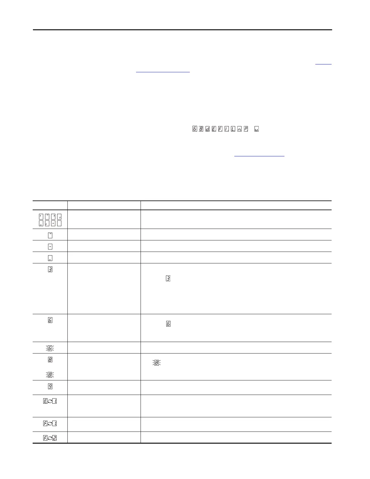
Table 15 - Error and Status Indication on the Seven-segment Display
Display Possible Cause Corrective Action
Power-up cycle — all segments are
activated sequentially.
No error
Object in protective field No error
Object in warning field 1 No error
Object in warning field 2 No error
Initialization of the device The display goes out automatically when the SafeZone Mini device has been initialized and/or the connection to
the second device has been made.
If the display does not go off:
• Check whether the partner device is in operation.
• Check the wiring.
If no partner device is connected:
Check the system configuration with the aid of the SCD software. Transfer the corrected configuration to the
SafeZone Mini device again.
Waiting for configuration or
configuration not completed
The display goes off automatically once the configuration has been successfully transferred.
If the display does not go off:
Check the system configuration with the aid of the SCD software. Transfer the corrected configuration to the
SafeZone Mini device again.
Waiting for restart of the device Switch off the voltage supply for the SafeZone Mini device for at least 2 seconds and then switch it back on.
or
Error of the external device monitoring
(EDM)
• Check whether the contactors are working correctly or if they are wired incorrectly and rectify any error.
• If is displayed: also switch off the voltage supply for the SafeZone Mini device for at least 2 seconds and
switch it back on.
Error in the control switch for restart or
reset
• Check the functionality of the control switch. The button may be defective or permanently operated.
• Check the wiring of the control switch for short circuit to 24V.
SafeZone Mini device has a malfunction
or is faulty
Switch off the voltage supply for the SafeZone Mini device for at least 2 seconds and then switch it back on.
If the display does not go off:
Send the SafeZone Mini device to the manufacturer for repair.
Overcurrent on OSSD connection 1 • Check the switching element connected (contactor, relay). Replace, if necessary.
• Check the wiring for short circuit to 0V.
Short circuit to 24V at OSSD connection 1 Check the wiring for short circuit to 24V.
 Loading...