Rockwell Automation Publication 442L-UM005B-EN-P - April 2017 65
Chapter 6
Application Examples and Connection
Diagrams
The examples that are shown are provided as an aid for your planning. You may
need to consider additional protection measures for your application.
Stationary Applications
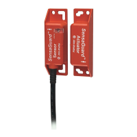
Figure 40 shows coverage of one area that a SafeZone™ Mini safety laser scanner
monitors permanently.
Figure 40 - Hazardous Area Protection with SafeZone Mini Device (Horizontal Mounting)
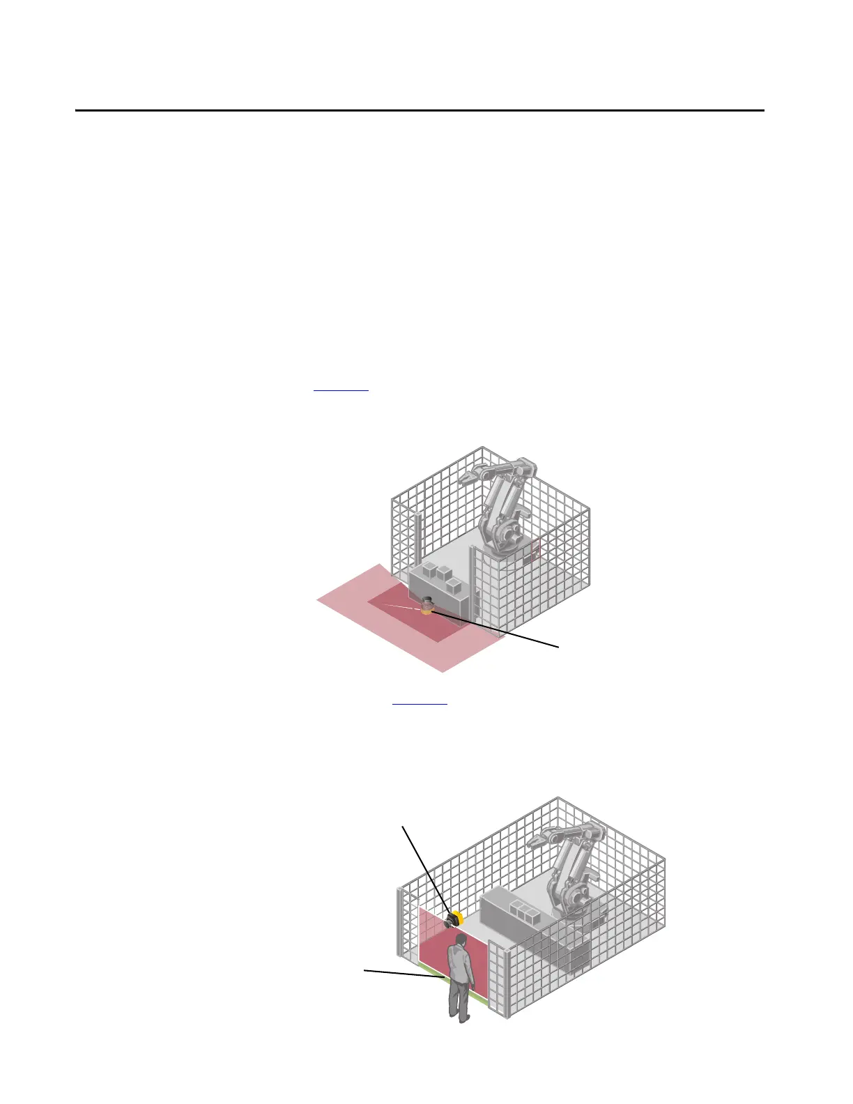
The access in Figure 41 is monitored permanently. For safety against
manipulation on the SafeZone Mini device, for example, the floor is used as a
reference. If the alignment of the SafeZone Mini device changes (for example,
due to changes to the bracket), it switches its OSSDs to the OFF state.
Figure 41 - Access Protection with SafeZone Mini Device (Vertical Mounting)
SafeZone Mini with one protective
field and one warning field —
mounted horizontally
SafeZone Mini with one
protective field —
mounted vertically
Floor as reference
 Loading...