52 Rockwell Automation Publication 442L-UM005B-EN-P - April 2017
Chapter 4 Mounting
Protective Field Width
The width of the protective field must cover the width of the vehicle and the
supplements for the measurement error and the lack of ground clearance.
Calculate the Protective Field Width S
B
See EN ISO 13855. Calculate the protective field width S
B
with the formula:
S
B
= F
B
+ 2 × (Z
G
+ Z
R
+ Z
F
)
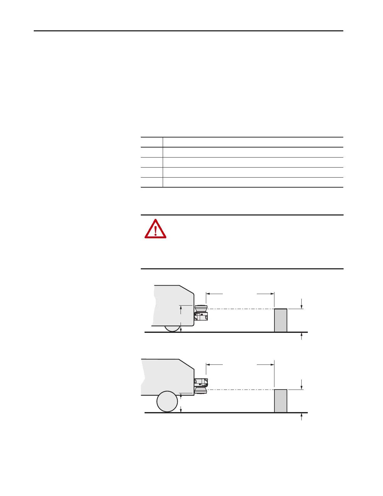
Height of Scan Plane
Figure 24 - Mounting Height [mm (in.)]
Variable Description
F
B
Vehicle width
Z
G
General safety supplement of the SafeZone Mini device = 100 mm (3.94 in.)
Z
R
Supplement for any reflection-related measurement error of the SafeZone Mini device
Z
F
Supplement for any lack of ground clearance of the vehicle
ATTENTION: Mount the SafeZone Mini device such that the scan plane is at a
maximum height of 200 mm (7.87 in.).
In this way, persons lying down are reliably detected. Tilting the protective
field so objects with a diameter of 200 mm (7.87 in.) are not detected, is not
allowed. We recommend aligning the scan plane horizontally at 70 mm
(2.76 in.).
TIP To produce the optimal scan plane, you can also mount the SafeZone Mini
device reversed.
Set protective
field length
190 (7.48)
150 (5.91)
Set protective
field length
110 (4.33)
150 (5.91)
 Loading...