68 Rockwell Automation Publication 442L-UM005B-EN-P - April 2017
Chapter 6 Application Examples and Connection Diagrams
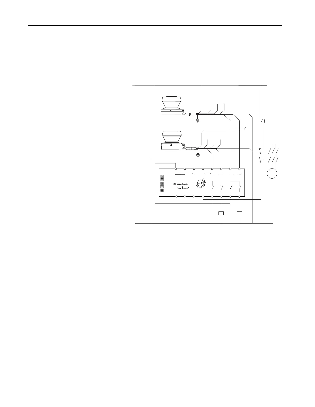
Two SafeZone Mini Devices with DI Guardmaster Safety Relay
Two SafeZone Mini devices that are connected to a DI Guardmaster safety
relay. The DI safety relay is configured for monitored manual reset. SafeZone
Mini scanners are configured for ON/OFF.
Figure 45 - Connection Diagram in Combination with a GSR DI Safety Relay
Power
In1
In2
Out
Logic
A2
A1
+
-
S11
S21
S12
S22
S32
S42
L12
L11
Y32
S34
13
14
23
24
24VDC
IN1
DI
IN2
0
1
2
3
4
56
7
8
LOGIC
Test Out
Reset
M
24V DC
0V DC
SafeZone Mini
SafeZone Mini
Shld
wire
Shld
wire
Wht*
Brn
Brn
Grn*
Yel*
Gry
Gry
Pnk
Pnk
Blu
Blu
K1
K2
L1
L2
L3
K1
K2
Monitored Manual Reset
Color
Pin
Signal
Wht 1
Output-Warning Field1*
Brn 2 +24V DC
Grn 3 Universal I/O1*
Yel 4 Universal I/O2*
Gry 5 OSSD 1
Pnk 6 OSSD 2
Blu 7 0V DC
Shld 8 Earth Ground
* not configured for
this application
no connection
Wht*
Grn*
Yel*
 Loading...