COOLING SYSTEM
RS 125
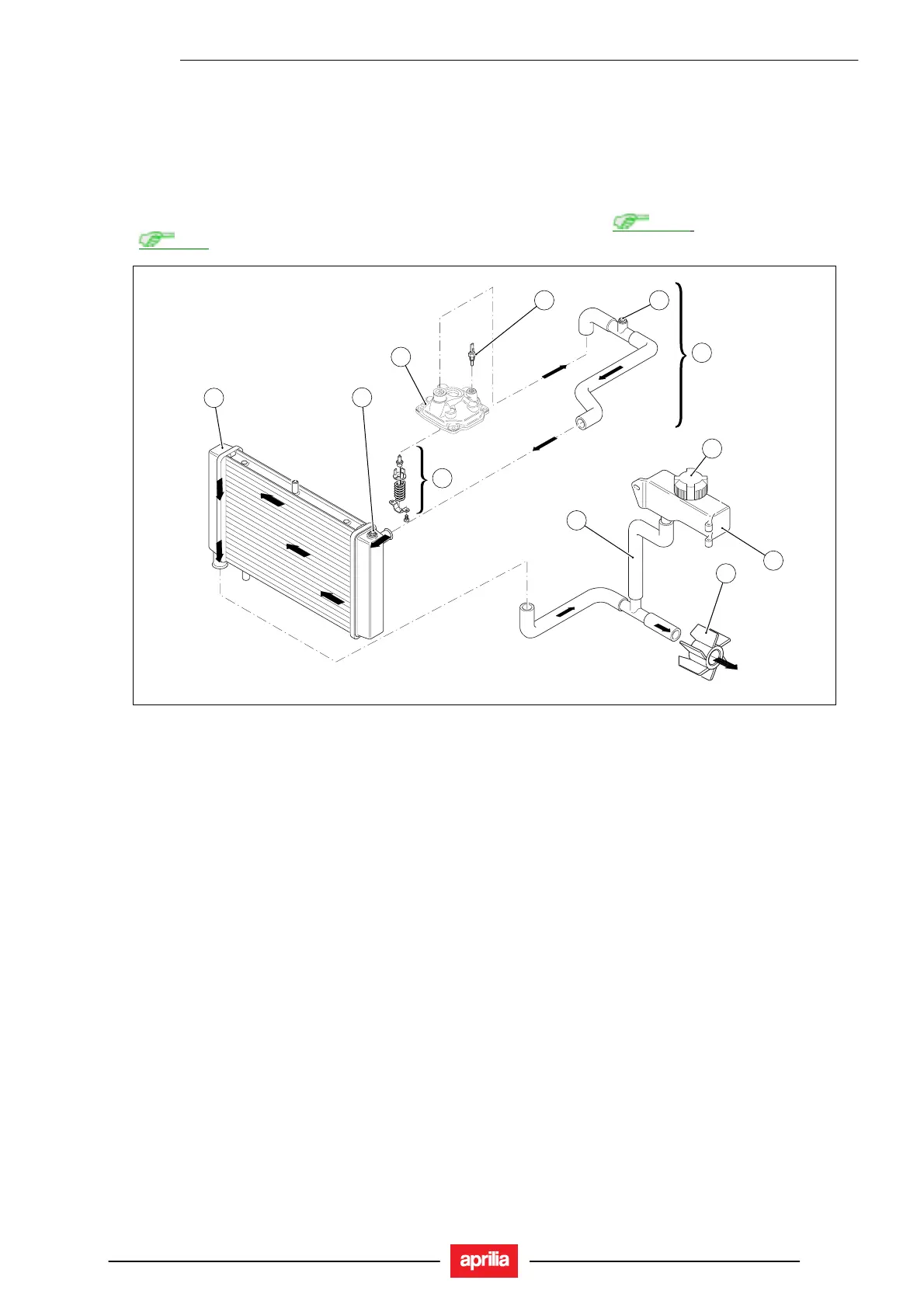
5.1. COOLING SYSTEM DIAGRAM
5.1.1. COOLING SYSTEM DIAGRAM
An engine-driven centrifugal pump accommodated in the engine circulates coolant through the system. The pump takes
in the coolant from the bottom section of the radiator and directs it through the ducts into the cylinders and cylinder
heads to cool down engine internals.
When coolant expands from heat, the expansion reservoir takes up excess coolant.
“LOW” and “FULL” level marks facilitate coolant level inspection and top-up; see
2.10.1.
See
1.3.1 for more details on coolant.
10
11
9
3
8
1
2
4
7
5
6
Key:
1. Cylinder thermistor
2. Expansion reservoir connection tubing
3. Plain radiator cap (no breather)
4. Radiator to thermal expansion valve tube
5. Centrifugal pump (intake)
6. Expansion reservoir
7. 70° thermostat
8. Breather union
9. Radiator breather
10. Radiator
11. Cylinder head cover
5 - 3
 Loading...