Home
APRILIA
Motorcycle
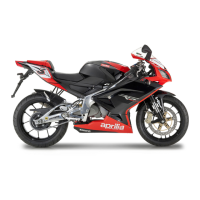
RS 125
APRILIA RS 125 User Manual
5
of 1
of 1 rating
290 pages
Give review
Manual
Specs
To Next Page
To Next Page
To Previous Page
To Previous Page
Loading...
CHASSIS
7 -
11
RS 125
7.1.6. WINDSCREEN
REMOVAL
•
Working from inside the front fairing, remove the seve
n
washers (1) and collect the seals (2).
•
Remove the seven retaining pins (3).
•
Remove the windscreen.
NOTE
Fit new washers (1) on assembly.
142
144
Table of Contents
General Information 1
8
Table of Contents
8
Manual Layout
9
Conventions Used in the Manual
9
Safety Information
10
General Rules
11
Basic Safety Rules
11
Dangerous Elements
14
Warnings Concerning Fuel, Lubricants, Cooland and Other Component Parts
14
Running-In
17
Running-In Recommendations
17
Vehicle Identification Data
18
Serial Numbers Location
18
Using Tools and Spare Parts
19
Spare Parts
19
Use of Products
20
Special Tools
21
General Tightening Torque Settings
22
Technical Data
23
Stands
25
Positioning the Vehicle on the Front Service Stand (Opt)
25
Positioning the Vehicle on the Rear Service Stand (Opt)
26
Products
27
Lubricant Chart
27
Decals Instructions
28
Routine Maintenance 2
32
Routine Maintenance
33
Introduction
34
Regular Service Intervals Chart
35
Points to be Lubricated
36
Multifunction Computer
37
Instruments and Indicators Table
40
Nut, Bolt, Screw Tightening
41
Fastening Elements
42
Battery
45
Checking and Cleaning the Terminals
46
Checking the Battery Electrolyte Level
47
Recharging the Battery
48
Long Inactivity of the Battery
49
Electrical Parts
50
Spark Plugs
51
Air Cleaner
53
Tubes
54
Fuel Tank
55
Lifting the Fuel Tank
55
Coolant
56
Checking and Topping up the Coolant Level
56
Clutch
57
Adjusting the Clutch
57
Brake Fluid
59
Checking and Topping up the Front Brake Fluid Level
59
Changing the Brake Fluid
61
Checking the Brake Pad Wear
62
Checking and Topping up the Rear Brake Fluid
63
Bleeding the Braking Systems
65
Adjusting the Rear Brake Control Lever
67
Adjusting the Gearbox Lever
68
Throttle
69
Idling Adjustment
71
Cold-Start Cable Play Adjustment
72
Front End
73
Steering
73
Front Suspension
74
Tail Section
75
Rear Swinging Arm Inspection
75
Rear Suspension
76
Rear Swinging Arm Adjustment
77
Inspecting the Rear Suspension Linkage System
78
Wheels
79
Tyres
80
Exhaust System
81
Exhaust Manifold Nuts
81
Drive Chain
82
Chain Slack Inspection
83
Adjusting the Drive Chain
84
Checking Chain and Sprockets for Wear
85
Cleaning and Lubrication
86
Chain Slider Inspection
87
Fuel System 4
94
Fuel Tank
95
Fuel Tank Removal
95
Draining the Fuel Tank
96
Complete Removal of the Fuel Cock
97
Air Cleaner
98
Airbox Removal
98
Air Cleaner Removal
99
Carburetor
100
Carburetor Removal
100
Removing the Fuel Feed Filter
101
Carburetor Specifications 1999-2002
102
Cooling System 5
104
Coolant
106
Coolant Change
106
Cooling System Diagram
106
Radiator
107
Thermistor
108
Coolant Thermistor
108
Thermostat
109
Expansion Reservoir
110
Engine 6
112
Exhaust System
113
Exhaust Pipe Removal
113
Engine
114
General Information
114
Engine Components that Can be Removed with the Engine Installed in the Frame
115
Engine Removal
116
Installing the Engine into the Frame
121
Rave
126
Rave Valve Specifications
126
Special Tools
127
Rave) Exhaust Valve Removal
128
Component Inspection
130
Rave) Exhaust Valve Installation
131
Table of Contents
134
Chassis
136
Chassis
137
Rider Seat Removal
138
Removing the Side Fairings
139
Air Dam Removal
141
Front Fairing Removal
142
Windscreen Removal
143
Fuel Tank Filler Cap Removal
144
Fuel Tank Fairing Removal
145
Seat Subframe Cover Removal
146
Tail Removal
147
Removing the Front Mudguard
148
Removing the Rear Mudguard
149
Removing the Seat End Cover
150
Removing the Number Plate Bracket
152
Chain Guard Removal
153
Upper Chain Slider Removal
154
Lower Chain Slider Removal
155
Air Scoop Removal
156
Electric Components
157
Battery Removal
157
Removing the Engine Control Unit
158
Voltage Rectifier Removal
159
Removing the Right-Hand Light Dip Switch
160
Removing the Left-Hand Light Dip Switch
161
Removing the Ignition Switch/Steering Lock
162
Removing the Instrument Panel
163
Headlight Removal
165
Removing the Front Direction Indicators
166
Removing the Rear Direction Indicators
167
Warning Horn Removal
168
Removing the Tail Light
169
Controls
170
Removing the Throttle Control
170
Removing the Throttle Cable from Intermediate Pulley to Oil Pump
171
Removing the Front Brake Control
172
Removing the Clutch Cable
174
Complete Removal of the Gear Shift Lever
175
Removing the Rear Brake Lever
176
Chassis
177
Removing the Handlebars
177
Removing the Instrument Panel Subframe
178
Removing the Seat Latch
179
Removing the Right-Hand Rider Footpeg Bracket
180
Removing the Left-Hand Rider Footpeg Bracket
181
Removing the Rider Footpeg
182
Removing the Passenger Footpeg Brackets
183
Passenger Footpeg Removal
184
Side Stand Removal
185
Seat Subframe Removal
186
Frame Removal
187
Frame Installation
190
Front Wheel
193
Front Wheel Diagram
193
Removing the Complete Front Wheel
194
Front Wheel Disassembly
196
Front Wheel Component Inspection
197
Refitting the Complete Front Wheel
198
Rear Wheel
200
Rear Wheel Diagram
200
Removing the Complete Rear Wheel
201
Rear Wheel Disassembly
203
Final Drive Removal
204
Inspecting the Rear Wheel Components
205
Refitting the Complete Rear Wheel
206
Front Brake
208
Front Brake Diagram
208
Replacing the Front Brake Pads
209
Front Brake Disc Inspection
210
Front Brake Disc Removal
211
Rear Brake
212
Rear Brake Diagram
212
Replacing the Rear Brake Pads
213
Rear Brake Disc Inspection
214
Rear Brake Disc Removal
215
Removing the Brake Master Cylinder
216
Steering
217
Steering Diagram
217
Headstock Removal
218
Component Inspection
219
Headstock Re-Assembly
220
Front Fork
221
Front Fork Diagram
221
Removing the Stanchion Tubes - Sliders
222
Disassembling the Stanchion Tubes - Sliders
223
Changing Front Fork Oil
225
Component Inspection
226
Stanchion Tube - Slider Assembly
227
Installing Stanchions and Sliders
228
Rear Swinging Arm
230
Removing the Rear Swinging Arm
230
Dismantling the Swinging Arm
232
Component Inspection
233
Reassembling the Swinging Arm
234
Installing the Swinging Arm
235
Rear Suspension
237
Rear Shock Absorber Removal
237
Rear Shock Absorber Installation
239
Removing the Rear Suspension Linkages
240
Dismantling the Rear Suspension Linkage System
241
Component Inspection
242
Drive Chain
243
Removing the Drive Chain
243
Refitting the Drive Chain
244
Electrical System 8
246
Layout of Components
247
Layout of Electrical Components
247
Foreword
248
Battery
249
Ignition System
251
Ignition System
253
Charge System
253
Charge System Layout and Power Supply
253
Starter Circuit
255
Sensors and Rev Counter
257
Sensors and Rev Counter Circuit
257
Visual and Acoustic Signals
259
Visual and Acoustic Signalling System
259
Brake Lights Circuit
261
Light Circuit
263
Rave Valve
265
Rave Valve Circuit
265
Stand
267
Stand Logic Circuit
267
Bulb Replacement
270
Replacing the Fuses
272
Beam Setting
273
Beam Height Setting
273
Wiring Diagram
274
Troubleshooting Information
279
Engine
279
Carburetor
281
Radiator
281
Electrical System
282
Battery
282
Brakes
283
Chassis
283
Hose Routing
284
Routing and Connections of Wiring, Cables and Hoses
284
Other manuals for APRILIA RS 125
Workshop Manual
194 pages
5
Based on 1 rating
Ask a question
Give review
Questions and Answers:
Need help?
Do you have a question about the APRILIA RS 125 and is the answer not in the manual?
Ask a question
APRILIA RS 125 Specifications
General
Brand
APRILIA
Model
RS 125
Category
Motorcycle
Language
English
Related product manuals
APRILIA RS 125 - 1998
88 pages
APRILIA RS 125 - 2006
80 pages
APRILIA RS 125 - 2002
88 pages
APRILIA RS 125 - 1995
92 pages
APRILIA RS 125 Euro 4
378 pages
APRILIA RS 125 - 02-2010
169 pages
APRILIA RS 125 - 01-2007
154 pages
APRILIA RS 125 TUONO - 2003
288 pages
APRILIA RS 50 - 1999
104 pages
APRILIA RS 250 - 1998
92 pages
APRILIA RS 660 2020
196 pages
APRILIA RS 660 2021
420 pages