COOLING SYSTEM
RS 125
5.5. THERMOSTAT
5.5.1. 70° THERMOSTAT
Read
1.2.1 and 1.3.1 carefully.
TORQUE WRENCH SETTINGS
Cylinder head cover screws (5): 10 Nm (1.0 kgm)
Thermostat bridge retaining screws (6): 6 Nm (0.6 kgm)
REMOVAL
• Drain all coolant from the cooling circuit; see
5.2.1.
• Remove the spark plug; see
2.6.1.
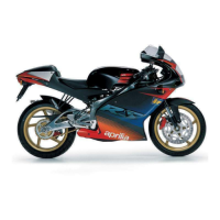
• Disconnect the electrical connector (1) at the thermistor
end.
• Slacken the clip (2).
• Withdraw the hose (3) from the cylinder head cover (4).
• Release and remove the four screws (5).
• Remove the cylinder head cover (4).
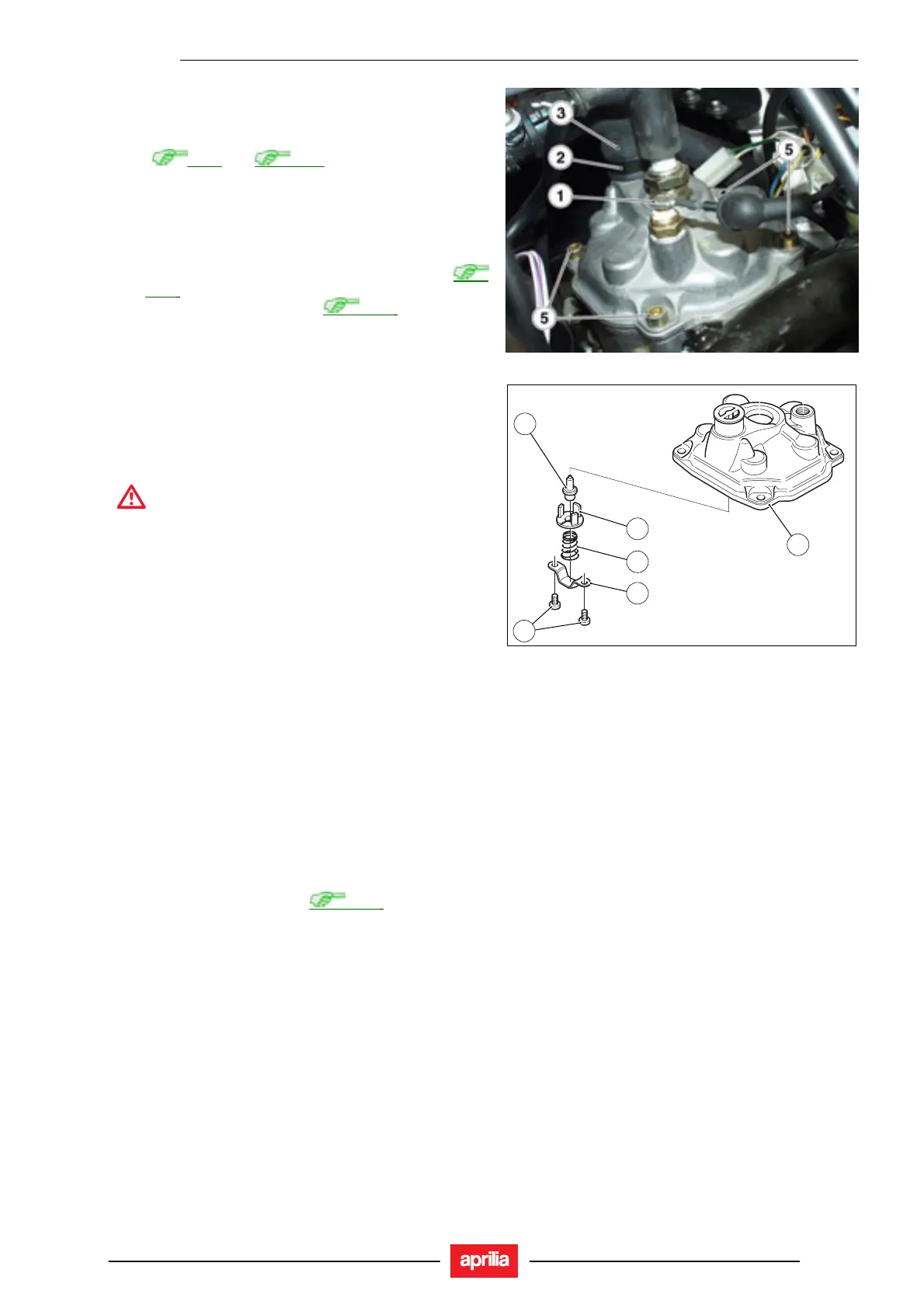
• Release and remove the two screws (6).
• Remove the thermostat (7) and collect bridge (10),
spring (9) and thermostat mount (8).
WARNING
Block off the openings to prevent the ingress of
dirt.
INSTALLATION
• Fit – in the order - thermostat (7), thermostat mount (8),
spring (9) and thermostat bridge (10) into the cylinder
head cover (4).
• Tighten the two screws (6).
• Refit the cylinder head cover (4).
• Tighten the four screws (5).
NOTE Be sure to have the special clip tweezers (no.
0277295) ready at hand and renew all clips using the same
type fitted originally.
• Refit the hose (3) into the cylinder head cover (4).
• Refit the spark plug.
• Connect the connector (1) to the thermistor.
• Fill the cooling circuit; see
5.2.1.
6
4
7
10
9
8
5 - 7

 Loading...