Rev D CHP Max DC Power Supply 5-3
Integrated management circuitry provides digital representations of internal temperature,
input voltage, power supply output voltages, and fan current for status monitoring.
Management signals enter and exit through the multi-pin connector on each power supply’s
rear panel.
Each CHP DC input power supply includes a power connector for the –48VDC input.
Detailed specifications for the power supplies are on page 5-18.
Connectors
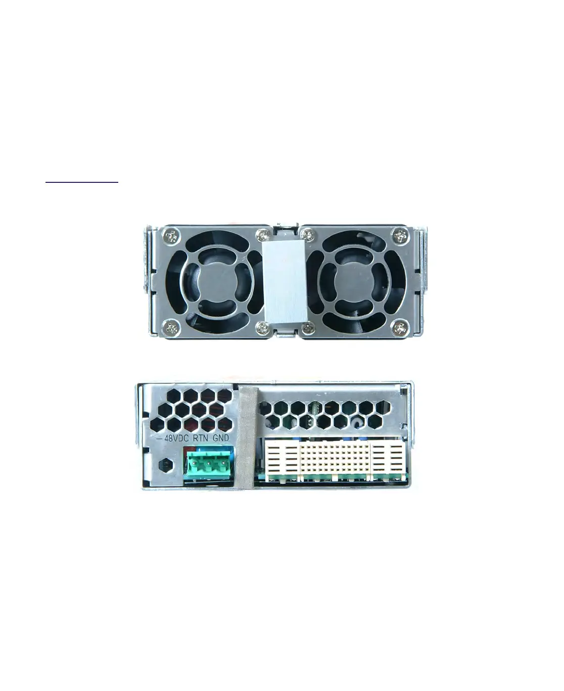
Figure 5.2
CHP DC Power
Supply Module Front
and Rear Views
Fan
DC Input Connector DC/Communication Connector
Front View (no connection points or status indicators)
Rear View
Fan

 Loading...