6-28 CHP Max™ Headend Optics Platform Chassis, Controllers and Power Supplies 1508685 Rev D
Setting Major and Minor Alarm Threshold Limits
The alarm parameters listed in Table 6.4 have four adjustable alarm thresholds and a fixed
deadband value associated with each parameter. Alarms generated by the status monitoring
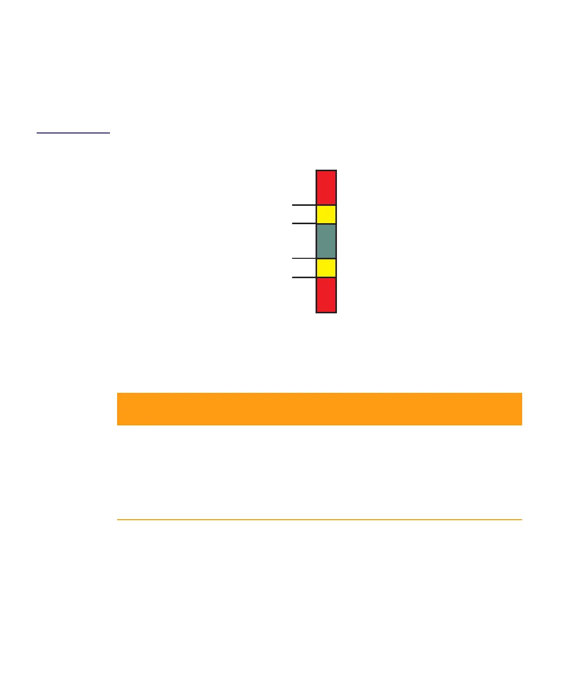
circuit are based on which thresholds have been exceeded. Figure 6.18 shows the four
threshold levels and the corresponding alarms.
Figure 6.18
Threshold/Alarm
Diagram
The factory-default threshold and deadband values for each parameter are listed in
Table 6.4. A deadband or hysteresis value prevents alarm oscillation. Once a threshold is
exceeded, the alarm can only be downgraded if the parameter is at least a deadband below
the threshold value.
➤ To adjust the alarm threshold limits
1. Follow the procedures for Local Monitoring with the CHP-CMS Craft Management
Software—page 1-12.
2. Double-click the CMM or CMM-1 module identifier in the module inventory or
double-click on the CMM or CMM-1 module in the image map to open that module’s
management window.
Table 6.4 Factory-default Threshold and Deadband Values
Parameter Major
Low
Minor
Low
Nomina
l
Minor
High
Major
High
Shutdown
Threshold
Deadband
+5 V
DC Output 4.7 4.9 5.25 5.6 5.7 6.7 1
–5 V
DC Output –5.6 –5.4 –5.1 –4.7 –4.5 –6.25 1
+12 V
DC Output 11.6 11.8 12.25 12.7 12.8 13.5 1
+3.3 V
DC Output 3.33.43.64.04.1 5.2 1
Internal Temperature
(°C)
0 15435057 — 1
Major High
Minor High
Minor Low
Major Low
Threshold
No Alarm (green)
Major (red)
Minor (yellow)
Alarm
Major (red)
Minor (yellow)

 Loading...