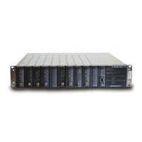
7-12 CHP Max™ Headend Optics Platform Chassis, Controllers and Power Supplies Rev D
DC Power
DC voltages from the power supply module(s) enter the SMM-2 through the multi-pin
DC/Communications connector.
Installation/Replacement of the SMM-2
Equipment Verification
Unpack and remove the module from the shipping box. Return the packing material to the
shipping container, and save it for future use. Verify that you have received the item shown
on the packing material list. If any item is missing or damaged, contact your ARRIS
representative or reseller for instructions.
Equipment Installation
To install the SMM-2:
1. Gently insert the SMM-2 into the slot just to the left of the power supply module(s).
Be careful to align the circuit card of the module with the metal guides on the top
and bottom of the chassis.
2. Carefully slide the SMM-2 into the chassis until it is fully seated in the backplane. The
latch on the front panel locks when the module is fully seated.
The SMM-2 is shipped with a default IPv4 address that must be changed by the operator as
soon as this card is accessed for the first time.
SMM-2 Factory Default network information:
Address Type Default Address
IPv4 address 192.168.1.1 (Ethernet RJ-45 connector)
10.10.10.1 (Ethernet over USB connector, configurable under CHP System
version 4.10 or later)
192.168.1.2 (Ethernet over USB connector, non-configurable under CHP
System version 4.9 or earlier)
Subnet Mask 255.255.255.0 (Ethernet RJ-45 and Ethernet over USB connector)
Default Gateway 192.168.1.254 (Ethernet RJ-45 connector)
Recommended Test
Manager IP Address
192.168.1.5 (Ethernet RJ-45 connector)
10.10.10.5 (Ethernet over USB connector, CHP System version 4.10 or later)
192.168.1.5 (Ethernet over USB connector, CHP System version 4.9 or earlier;
refer to the following Note)

 Loading...