Rev D System Management Module 2 (SMM-2) 7-9
Indicators and Connectors
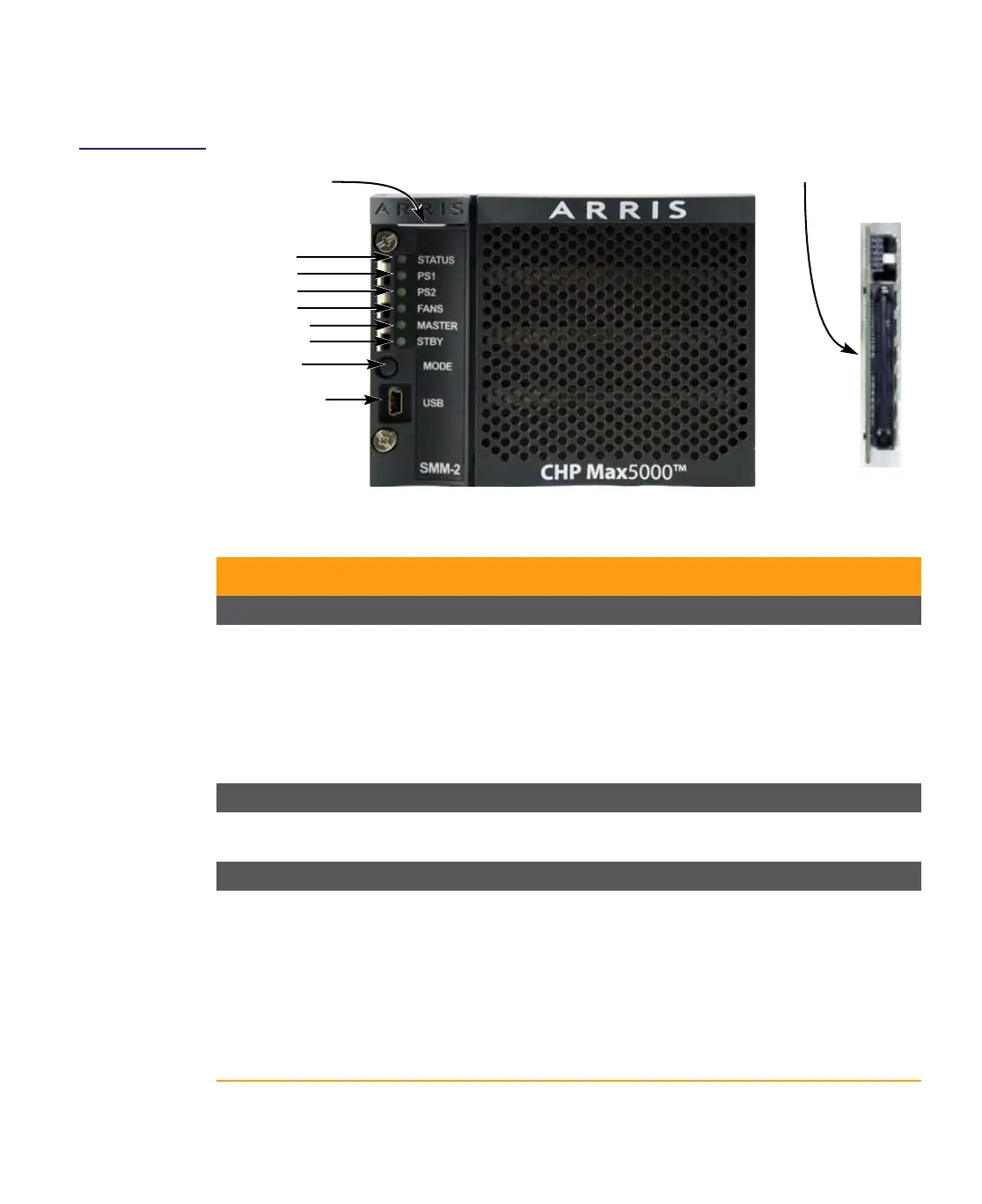
Figure 7.3
SMM-2 Front and
Rear Panels
Table 7.2 SMM-2 Connectors and Status Indicators
Connector/LED Description
Front Panel Connector
Mini-USB Connector Mini-USB connector. Connects to a laptop computer to provide an interface
as a transport for protocols like Ethernet (Ethernet Over USB) or serial
(Serial Over USB) devices.
In order to use the SMM-2 mini-USB front panel connector, the computer
connected to the mini-USB connector must have special drivers installed in
its operating system. Those drivers are contained in the drivers directory on
the CD-ROM for CHP Max5000 System.
Rear Panel Connector
DC / Communication
Connections
Multi-pin connector. Connects to chassis backplane. Carries DC power and
communication signals into and out of the module.
Front Panel Indicators
Status LED Indicates the overall status of chassis, all other installed modules,
backplane voltages, and internal temperature. Any minor or major alarms
within any power supply or application module is also indicated.
■ Solid Green = All monitored functions within defined limits.
■ Solid Yellow = One or more functions operating beyond minor alarm
threshold but has not exceeded the major threshold.
■ Solid Red = One or more functions operating beyond major threshold.
■ Off = Not defined.
■ Blinking (any color) = LED blinks during initialization process.
Front View
PS 2
Fans
Master
Mini-USB
Connector
Status
PS 1
Latch Release
Standby
LED Indicators
Rear View
DC / Communications Connections
Mode

 Loading...