Rev D CHP Max5000 Chassis (Rear Fiber Version) 2-1
CHAPTER 2
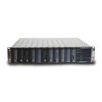
CHP MAX5000 CHASSIS (REAR FIBER VERSION)
This chapter describes the rear fiber version of the CHP Max5000 chassis.
Equipment Description —page 2-1
Tools and Materials—page 2-3
Unpacking—page 2-3
Precautions—page 2-4
Chassis Options—page 2-4
Connectors and Additional Assemblies—page 2-5
Module Locations—page 2-7
Functional Description—page 2-8
Handle Kit Installation —page 2-9
Offset Bracket Kit Installation —page 2-10
Tablet PC Installation Requirements—page 2-11
CHP Chassis Installation—page 2-11
Configuring the CHP Chassis —page 2-13
Module Installation — page 2-13
Maintenance —page 2-16
Backplane Ethernet Switch—page 2-25
Equipment Description
The CHP Max5000 chassis mounts directly in a 19-inch rack or in a 23-inch rack using an
optional bracket kit (P/N CHP-EXTBKT-23). The 2RU (3.5in. [8.9cm]) chassis holds up to 10
application modules, 2 power supply modules, and 1 management module. Eight
independent field-replaceable fans are mounted on the rear of the chassis to force air from
the front of the modules through the rear of the chassis to cool the application modules. In
order to reduce the noise level generated by the eight single-speed fans in the original
chassis, dual-speed fans have been used in all subsequent chassis. The speed of each
dual-speed fan is determined by the ambient air temperature surrounding that fan. These
fans operate at the quieter low-speed when the ambient temperature is below
approximately 30° C (86° F) and operate with a higher noise level in high-speed mode when
the ambient temperature is above approximately 30° C (86° F). To achieve full noise

 Loading...