5-2 CHP Max™ Headend Optics Platform Chassis, Controllers and Power Supplies Rev D
Equipment Description
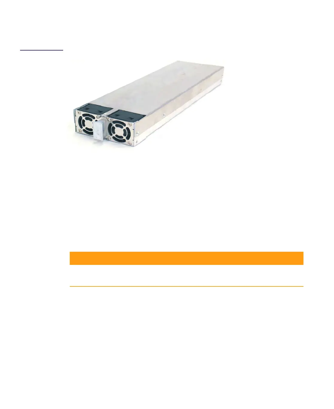
Figure 5.1
DC Power Supply
The CHP Max DC power supply (P/N CHP-PS/DC1) can no longer be purchased; it has been
replaced by the P/N CHP-PS/DC1-Q power supply with identical specification but using a
dual-speed fan to allow operation at a reduced noise level and P/N CHP-PS/DC1-SW high
wattage power supply.
The low noise power supply operates in the low speed mode when the ambient temperature
surrounding the power supply is less than 31°C and operates in the high speed mode when
the ambient temperature is above 31°C. To achieve full noise reduction, the chassis with
eight quieter dual-speed fans (CHP-CHASSIS-19Q) must also be used.
The CHP Max DC power supplies (P/N CHP-PS/DC1-Q and P/N CHP-PS/DC1-SW), are efficient,
switched-mode modules that accept DC input from –72 to –36V
DC. This hot-swappable
module produces 250 and 475 watts respectively to provide the DC power required to
operate one fully-loaded chassis of application modules.
All application module configurations can operate properly with one CHP-PS/DC1,
CHP-PS/DC1-Q, or CHP-PS/DC1-SW module installed. Two power supply modules can be
installed to provide load sharing and redundancy. Isolated outputs allow the primary and
redundant supplies to operate in a power-sharing configuration. Should the primary power
source fail, a second power supply provides all necessary DC power. The power supply
module(s) is located on the far right side of the chassis behind the Craft Management
module (CMM) or system management module (SMM).
This module converts the –48VDC input into four DC voltages: +12.0VDC, +5.0VDC, +3.5VDC,
and –5.0VDC, which are isolated from the –48-volt bus. These voltages pass through the DC
output connector on the rear of the power supply to the chassis backplane, which routes
them to installed application modules.
+12.0 VDC +5.0 VDC +3.5 VDC –5.0 VDC
CHP-PS/DC1-Q 10 Amps 22 Amps 2.2 Amps 1.8 Amps
CHP-PS/DC1-SW 24 Amps 31 Amps 5 Amps 2 Amps

 Loading...