6-8 CHP Max™ Headend Optics Platform Chassis, Controllers and Power Supplies 1508685 Rev D
Functional Description
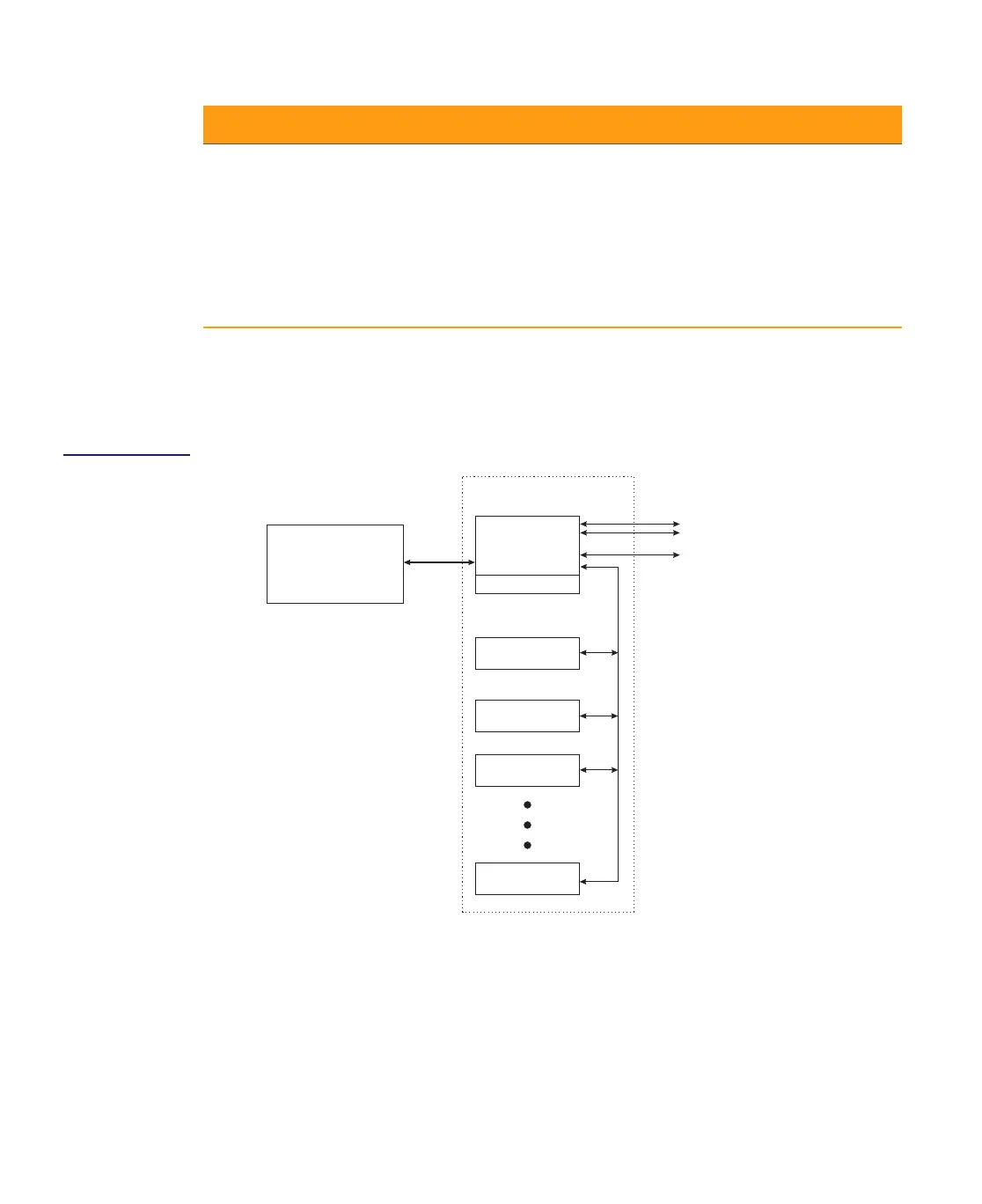
Figure 6.4
CHP Max Local
Management and
Monitoring
Communication Signals
RS-232 between Craft Management Software and CMM
The Craft Management Software, installed on a computer connected to the CMMs Craft
interface port, sends requests for information to the CMM. The CMM returns information
received from application modules back through the RS-232 interface port for display on the
Craft Management Software.
Lock/Local LED Indicates the status of user controls on chassis and modules, as well
as the state of the RS-232 communications port.
■ Solid Green = All user controls within the chassis have been
disabled (locked) via the Craft software
■ Solid Yellow = RS-232 Craft interface connector is active and
disables (locks) SNMP access to chassis via RS-485 connection
on the rear panel of chassis. Used when chassis are connected
in a daisy chain and one SMM module is installed.
■ Off = All user-set controls are unlocked and available.
Table 6.2 CMM and SMM/SMM-1 Connectors and Status Indicators
Connector/LED Description
CMM or SMM
Power
Supply
Application
Module 1
Application
Module 2
Application
Module 10
Fans
SMM Interface
(SMM only)
Ethernet
Local
Computer with CHP
Craft Management
Software
CHP Max5000 Shelf
RS-232
SPI Bus
Shelf Interconnect
RS-485
RJ-45

 Loading...