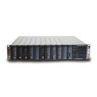
2-6 CHP Max™ Headend Optics Platform Chassis, Controllers and Power Supplies Rev D
Table 2.4 CHP Max5000 Chassis Connectors and Fans
Connectors Description
DC/Communication
Connectors
Multi-pin connectors on chassis backplane carry DC power (via DC bus)
and communication signals (via SPI bus) into and out of application
modules.
Shelf Interconnect On all models except the CHP-CHASSIS-19U, RJ-14 connectors permit
“daisy-chaining” up to 10 chassis together for remote monitoring of
these chassis. One SMM module is required to interface with up to 9
CMM-equipped chassis. For best performance, ARRIS recommends
daisy-chaining a maximum of 5 chassis together; 6 to 10 may be
daisy-chained together, but it will impact performance.
Hi Speed Shelf Interconnect On model CHP-CHASSIS-19U only, RJ-14 connectors permit
“daisy-chaining” up to 10 chassis together for remote monitoring of
these chassis. One SMM module is required to interface with up to 9
CMM-equipped chassis. Intended for high speed applications;
requires installation of optional Backplane Ethernet Switch P/N
CHP-BP-ETH-SW. For best performance, ARRIS recommends
daisy-chaining a maximum of 5 chassis together; 6 to 10 may be
daisy-chained together, but it will impact performance.
Lo Speed Shelf Interconnect On model CHP-CHASSIS-19U only, RJ-14 connectors permit
“daisy-chaining” up to 10 chassis together for remote monitoring of
these chassis. One SMM module is required to interface with up to 9
CMM-equipped chassis.
Ethernet SNMP Interface
(10 BaseT)
An RJ-45 interface carries management signals from the chassis to a
remote EMS controller.
Local Alarm Terminal Block Access terminals for external alarms. Please note that the contacts
on the terminal block are reversed.
RF Connector Locations RF connectors on rear of application modules slide through these
holes in the chassis. Additional hardware is required to secure
application modules.
Ground Studs Connect to earth ground.
Retaining Tabs Secure power supply modules; press tab to remove power supply.
Fan Assemblies Eight independent, field-replaceable assemblies (single-speed P/N
0625734-1; dual-speed P/N CHP-QFANKIT) for cooling.

 Loading...