Rev D CHP Max5000 Chassis (Rear Fiber Version) 2-23
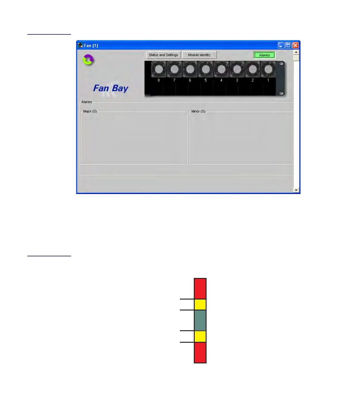
Figure 2.13
Chassis Fan Bay
Alarm Tab Display
Setting Major and Minor Alarm Threshold Limits
The alarm parameters listed in Table 2.10 have four adjustable alarm thresholds and a fixed
deadband value associated with each parameter. Alarms generated by the status monitoring
circuit are based on which thresholds have been exceeded. Figure 2.14 shows the four
threshold levels and the corresponding alarms.
Figure 2.14
Threshold/Alarm
Diagram
Major High
Minor High
Minor Low
Major Low
Threshold
No Alarm (green)
Major (red)
Minor (yellow)
Alarm
Major (red)
Minor (yellow)

 Loading...