Rev D CHP Max AC Power Supply 4-11
➤ To adjust the alarm threshold limits
1. Follow the procedures for Local Monitoring with the CHP-CMS Craft Management
Software—page 1-12.
2. Double-click the PS module identifier in the module inventory or double-click on the
desired power supply module in the image map to open that module’s management
window.
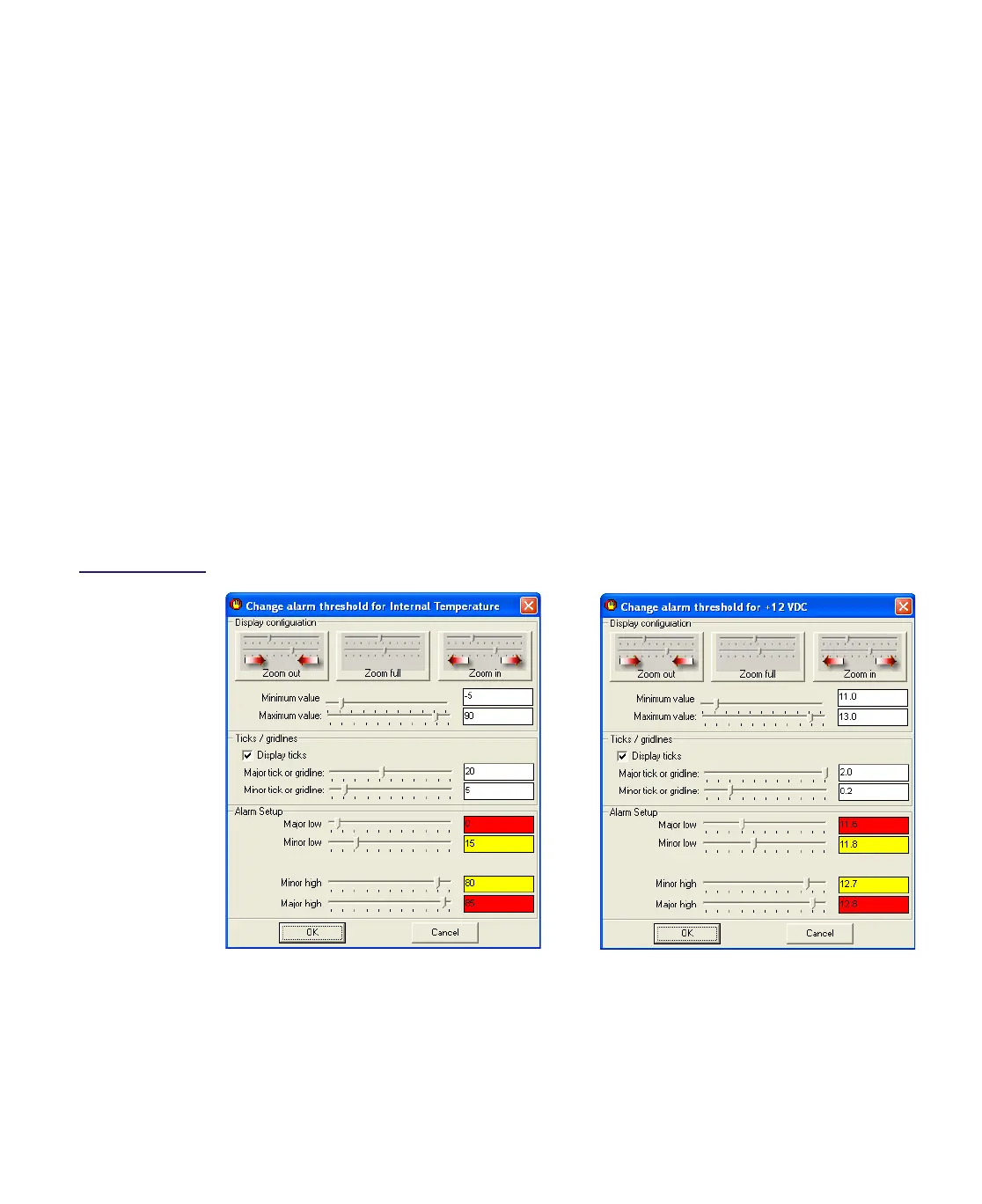
3. Right click on the Internal Temperature meter and select
Configure from the shortcut
menu. Refer to Figure 4.8.
4. In the Alarm Setup area, drag the slider or enter the desired alarm limit value for the
Major low, Minor low, Minor high, and Major high. Click
OK to save these alarm limit
values.
5. Right click on the +12 VDC meter and select
Configure from the shortcut menu. Refer
to Figure 4.8 on page 4-11.
6. In the Alarm Setup area, drag the slider or enter the desired alarm limit value for the
Major low, Minor low, Minor high, and Major high. Click
OK to save these alarm limit
values.
7. Repeat Steps 5 and 6 to the +5 VDC, +3.3 VDC, and –5 VDC meters if you want to
adjust these alarm threshold values.
Figure 4.8
Internal
Temperature and
+12V
DC Threshold
Limits
+12VDC Alarm Threshold Settings
Internal Temperature Alarm Threshold Settings

 Loading...