106
COMPACT VOICE ALARM SYSTEM
SERVICE MANUAL
12.3.10 xCtrLine-2 / 4
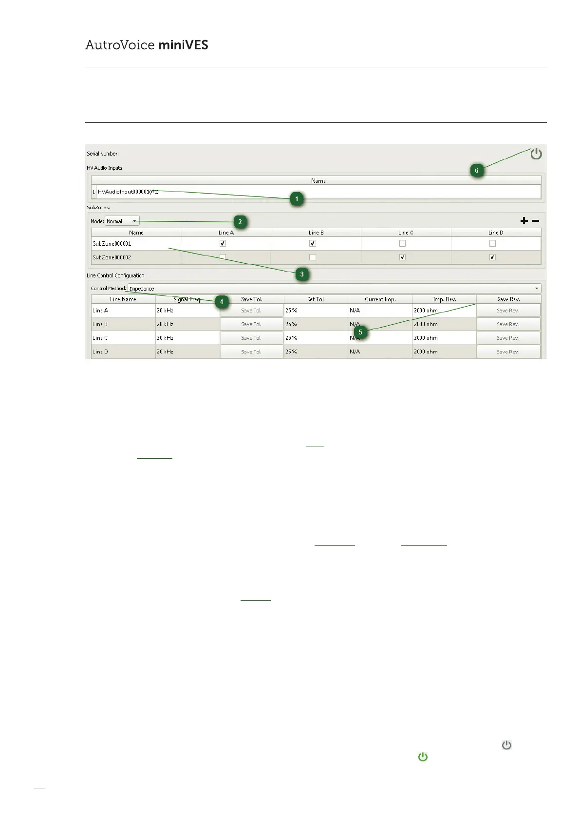
1
HV Audio Inputs
The name eld enables to assign an individual name to the input intended to receive a 100 V signal from an amplier output.
The name is shown on the main AudIO-4/12 editing window, in the Connection tab.
2
SubZones / Mode:
Mode enables switching the card into following modes: Loop – the system detects short circuit / open line as well as ground
leakage; Regulator – the volume control mode on the speaker line.
3
SubZones
Speaker zone editing window. It enables changing of the generic name of a zone by double-clicking the name. In addi-
tion, itis possible to dene which speaker line outputs (A,B,C,D) are assigned to a given zone. Any combination is possible,
however the default settings are accordant with the EN54-16, EN54-4 standards and assign two outputs per each zone.
4
Line Control Conguration / Control Method:
Speaker line supervision method window – options include: Impedance method and Switching o the speaker line supervision.
5
Save Rev.
If the system is supposed to supervise speaker lines by means of the impedance method, having loaded a conguration into the
system and connected a speaker line of a properly matched power and free of ground faults, load the impedance reference for
a given line. In order to do this, select the Save REV button. From now on, the system properly supervises the operation of the speaker
line. The impedance method continuously measures the impedance of the speaker line and if the value set in the tolerance window
has been exceeded, an error is reported. The impedance method is equipped with a number of algorithms to minimize reporting
untrue faults resulting from abrupt temperature changes which aect line impedance, as well as sudden changes of impedance itself.
Adequate impedance measurement range on a single speaker line starts at 12.5, and ends at 10 k, for measured frequency of
20kHz. A 4-output xCtrLine-4 card (A,B,C,D) can be loaded up to 800 W of total power, the maximum load for a single speaker line is
300 W. In the case of a bridged connection of outputs A+B and C+D, themaximum tolerated power for each pair is 450 W. for a 2-out-
put xCtrLine-2 card (A,B), the correct impedance measurement range on a single speaker line is minimum 12.5 , max 10k ohm, for
the reference frequency of 20 kHz. A 2-output card can be loaded up to 400 W of total power, the maximum load for a single speaker
line is 300 W. In the case of a bridged connection of outputs A+B and C+D, the maximum supported power for each pair is 450 W.
6
On-line mode
The on-line mode enables to view the impedance values, as measured, as well as record reference impedance into the control
card. Having loaded a conguration into the system, a single click on the left mouse button on the grey icon results in
entering the real-time view mode and change of the colour of the icon into bright green . A change of tolerance, reference
impedance or real-time measurement must be preceded by entering into the on-line mode.
 Loading...