59
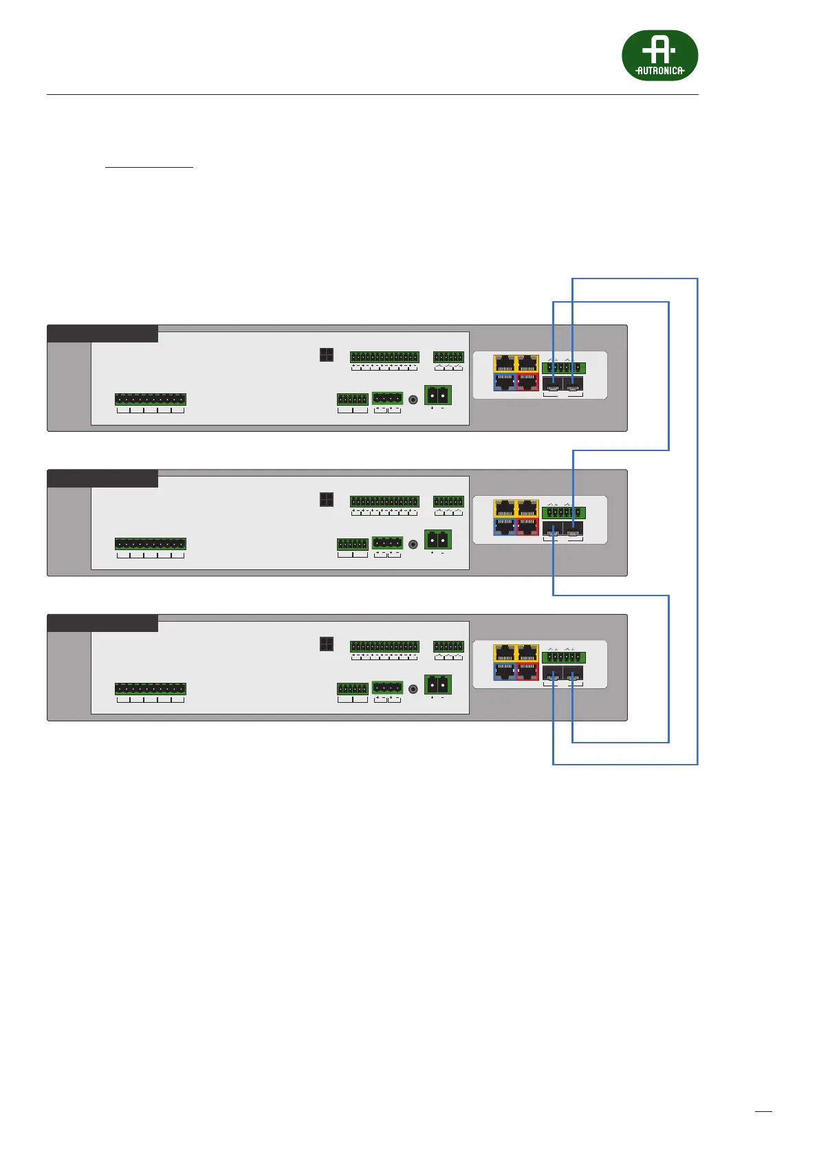
7.3.1.2 Ring Topology
In RING topology, the connection between system elements is redundant. The cables form a single continuous pathway for
signals through each node – a ring. In the event of cable/communication optic ber damage, the system still functions by using
the remaining part of the ring.
Drawing 34.
BUS1 BUS2
IN7IN6IN5IN4IN3IN2IN1
+48 VDC BATT
Audio IN Audio OUT
C
LR
C
LR
+24 VDC
150 mA
+48 VDC
350 mA
TEMP.
SENSOR
LINE ALINE BLINE CLINE DHV AUDIO IN
C
H
C
H
C
H
C
H
C
H
LAN/WANRS485
LANLAN PoE
IN1IN2
BA
FIBER
1
AV miniVES 2001N
OUT3OUT2OUT1
BUS1 BUS2
IN7IN6IN5IN4IN3IN2IN1
+48 VDC BATT
Audio IN Audio OUT
C
LR
C
LR
+24 VDC
150 mA
+48 VDC
350 mA
TEMP.
SENSOR
LINE ALINE BLINE CLINE DHV AUDIO IN
C
H
C
H
C
H
C
H
C
H
LAN/WANRS485
LANLAN PoE
IN1IN2
BA
FIBER
1
AV miniVES 2001N
BUS1 BUS2
IN7IN6IN5IN4IN3IN2IN1
+48 VDC BATT
Audio IN Audio OUT
C
LR
C
LR
+24 VDC
150 mA
+48 VDC
350 mA
TEMP.
SENSOR
LINE ALINE BLINE CLINE DHV AUDIO IN
C
H
C
H
C
H
C
H
C
H
LAN/WANRS485
LANLAN PoE
IN1IN2
BA
FIBER
1
AV miniVES 2001N
OUT3OUT2OUT1
OUT3OUT2OUT1
RING topology control units connection (ber connection)
Note: this connection type applies only to xxxxN and xxxxLN series units. These devices are equipped with the xNet_mini1Gb/
WAN/RS network card providing slots for two SFP modules.
 Loading...