87
12.3 System Conguration
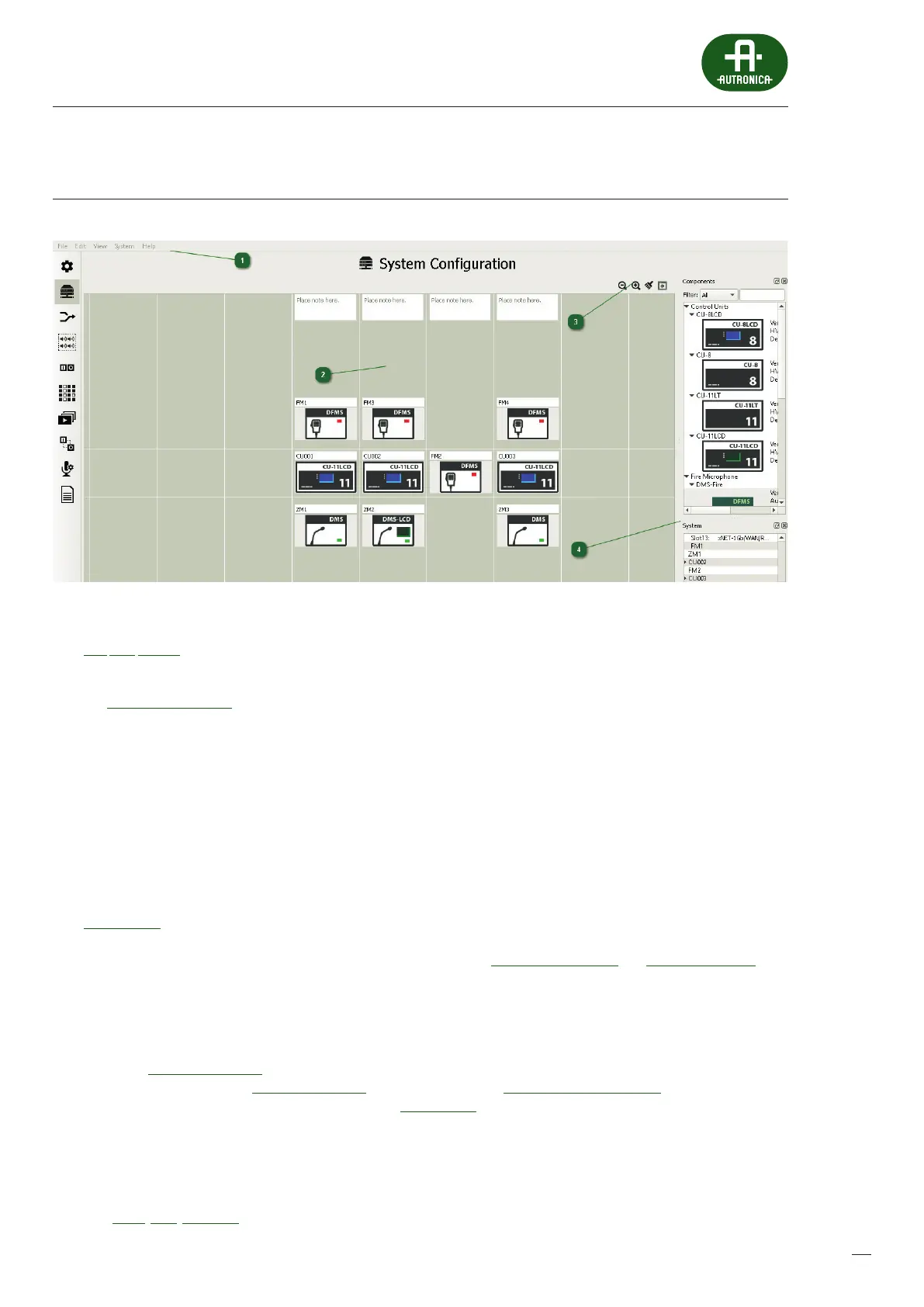
1
Main Menu bar
File, Edit, System
2
Workspace
The System Conguration tab is one of the most important items in the AutroVoice miniVES system conguration software.
The main window, called Workspace, represents system connections by means of vertical and horizontal lines. Placing
devices along a vertical line represents a copper wire connection within a single location. The horizontal space between
the two lines in the center of the workspace represents a ber optic connection. Devices placed next to each other within
this space ale connected by a ber optic link and are often separated by a greater distance. Additionaly, all of the connections
upwards from the central ber connection part of the workspace are monitored – the system checks for device and link fault.
The system elements placed below the cenral eld (zone microphones) will not be monitored.
3
Components
In the top right part of the work eld there is the tab with all available elements of the AutroVoice miniVES system –
theComponents tab. Upon starting a new system design, the rst component you should drag and drop to the workspace
(the congurator will suggest and highlight a proper eld) is the central unit. In order to nd it press the arrow next to
Control Units in the components tab and a list of available units will drop down, next simply use the drag & drop method.
The software suggests, with a grey rectangle, where a given element can be placed only if the cursor with the element
being drawn is located within the work eld. Repeat the procedure for Fireman Microphones and Zone Microphones tabs.
4
System
In the bottom right part of the work eld there is the tab System. This tab is used for detailed conguration of the devices
and shows allocation of cards in individual control unit slots. Having added a control unit to the work eld, the name of the
unit will appear in the system tab, as well as a triangle icon meaning a drop-down list. Right-clicking on the name displays
the option Go to conguration. When the list drops down, a list of available slots will be displayed. Right-clicking on a slot
displays additional option of Go to conguration (card detailed editing), Add Control/Function Card – adding a card to an
empty slot or changing allocation of the card in the slot, Remove Card – removal of a card which was assigned to a slot before.
In addition, detailed editing of elements from the work eld may be triggered by double-clicking of the left mouse button
on each of the devices in the work eld. If the device contains more elements to be congured, as in the case of control units,
then the rst double click of the left mouse button results in moving to the next level of editing where we can see all dened
cards in a unit. A next double click on any available element means moving to the detailed parameter card of a given element.
A detailed description of the editing window for individual elements of the AutroVoice miniVES system is available in the following
tabs: DFMS, DMS, xCtrLine-4.
 Loading...