55
Connection Diagram
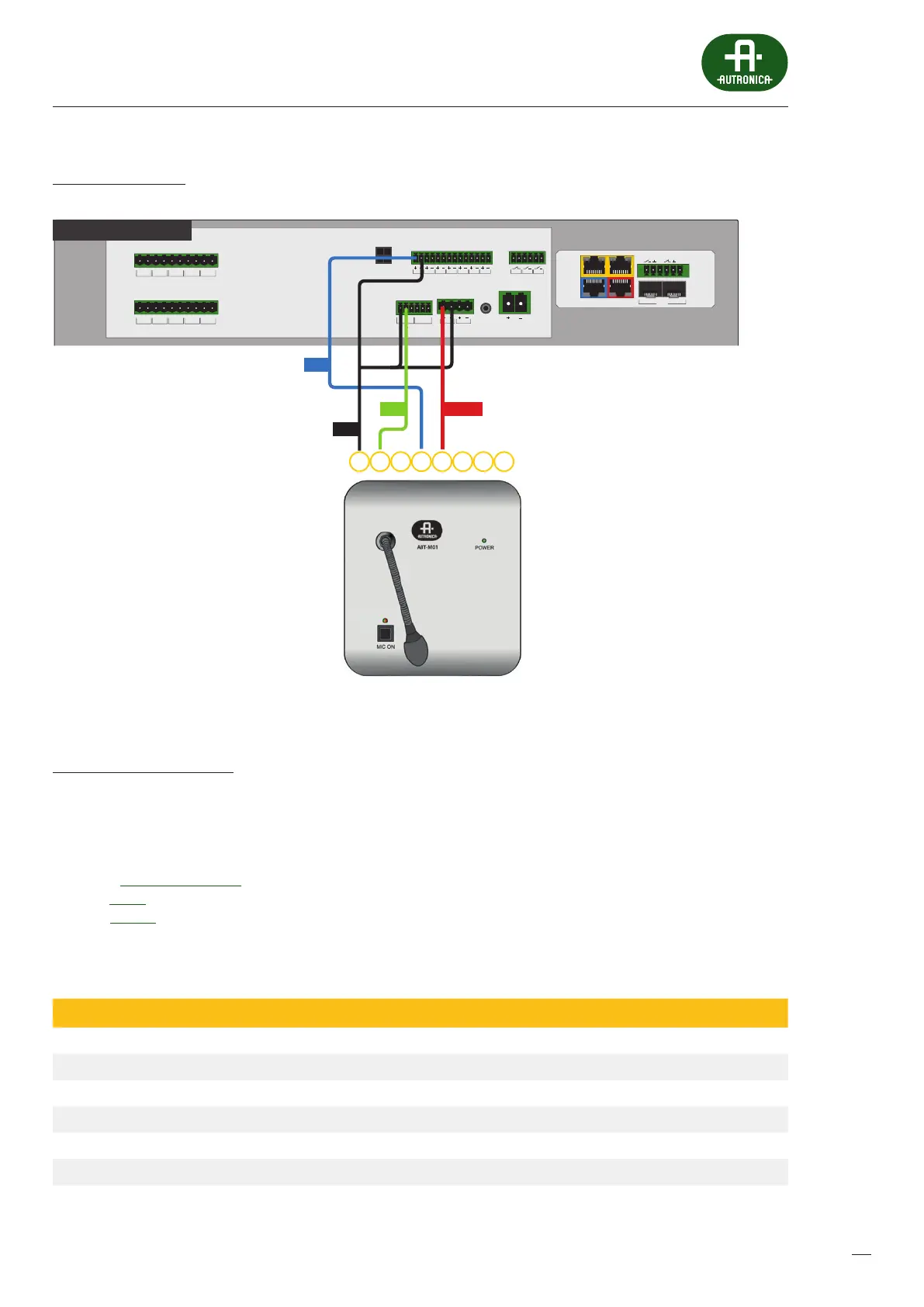
Drawing 31.
BUS1 BUS2
IN7IN6IN5IN4IN3IN2IN1
+48 VDC BATT
Audio IN Audio OUT
C
LR
C
LR
+24 VDC
150 mA
+48 VDC
350 mA
TEMP.
SENSOR
LINE ALINE BLINE CLINE DHV AU DIO IN
C
H
C
H
C
H
C
H
C
H
LINE ALINE BLINE CLINE DHV AU DIO IN
C
H
C
H
C
H
C
H
C
H
LAN/WANRS485
LANLAN PoE
IN1IN2
BA
FIBER
2
1
AV miniVES 4001LN
OUT3OUT2OUT1
1234 6785
PTT
GND
OUT POWER
Connecting the ABT-M01 microphone to AutroVoice miniVES
AutroVoice miniVES settings
» Change the generic name of the Audio input no.3 to Local Audio IN
» Create a Zone group – All Zones and add all of the available zones
»
Create a new matrix and name it Microphone – add the Local Audio IN input from the available Audio inputs eld
andthe All zones zone group
» In the Events Conguration tab assign the following events to Logical input INPUT1, contact mode:
Active – General – add the Microphone matrix (start)
Inactive – add the Microphone matrix (stop)
Table 13. Technical data of ABT-M091 microphone
Model ABT-M01
Eciency, mV / Pa 10
Output level, mV 775
Maximum distance from amplier, m 250
Recommended cable type UTP
Connector Type 8P8C (RJ45)
Dimensions without packaging (not more than), mm 150 x 60 x 165
Net weight (not more than), kg 1,2
 Loading...