9. Convergence
Convergence test pattern
4
1
2
5
3
6
3
6
2
5
4
1
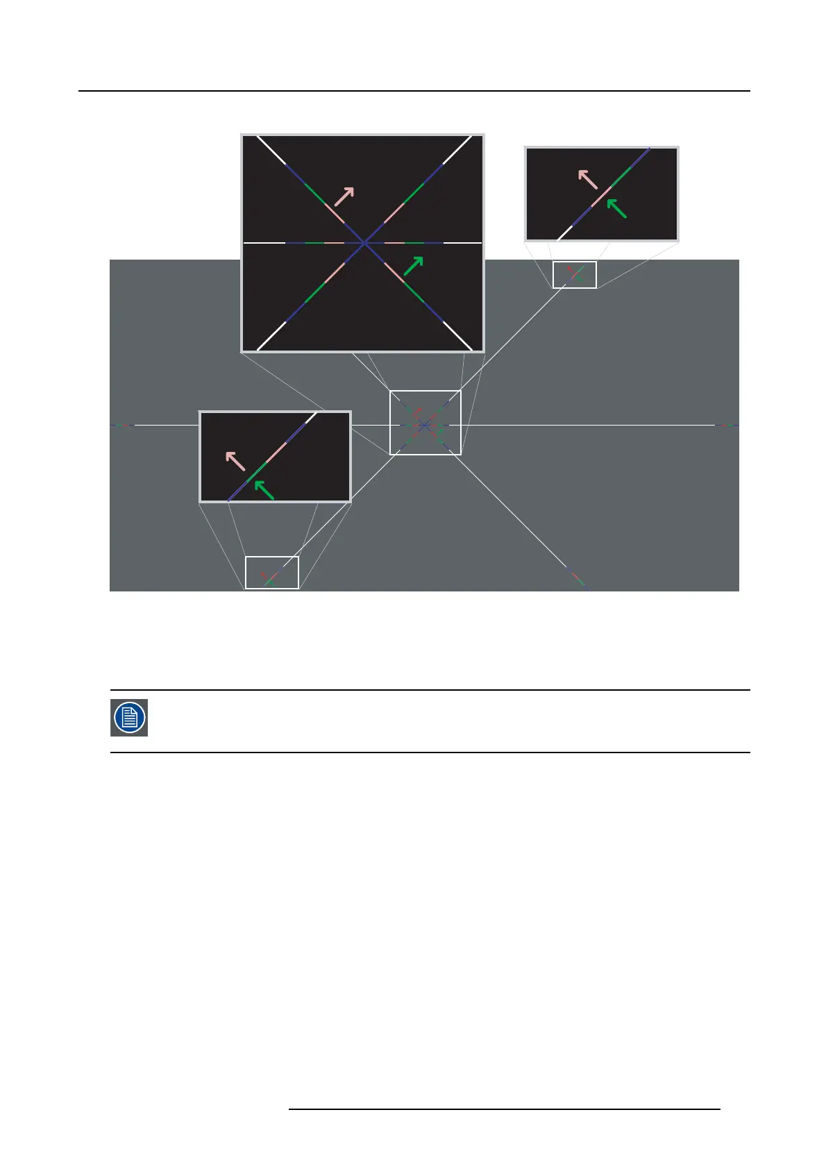
Image 9-2
Convergence test pattern
The test pattern illustrated above is specially designed for convergence purp oses. The test pattern has three red arrows numbered
from 1 to 3 and three green arrows num bered from 4 to 6. These numb ers and c olors correspond w ith the numbers and colors of
the ex tended control knobs (image 9-1). The direction of the arrow shows the m ovem ent of the channel color (red or green) when
turning the cor responding knob in the direction indicated by t he arrow m arked on the kno b.
The three convergence control knob
s of one chan nel stand in relation with each other. So , a chan ge to one
of them will also effect the adjustment results of the two others. Therefore, all three control knobs have to
be alternately and repeatedly adjusted un til the pro jected color is perfectly converged with the blue reference
color of the test pattern.
Adjustment range
• The adjustment r ange is limited to approximately 30 pixels in both directions.
• One turn (360°) of a control knob relates to an app roximately 30 pixel displac ement on the screen.
• When changing the adjustment direction there w ill be s ome play of approximately one turn (360°).
R5905043 DP2K-12C/11CX 19/02/2018
161
 Loading...


