17. Lamp power supply
17.2 L PS diagnostic LED’s
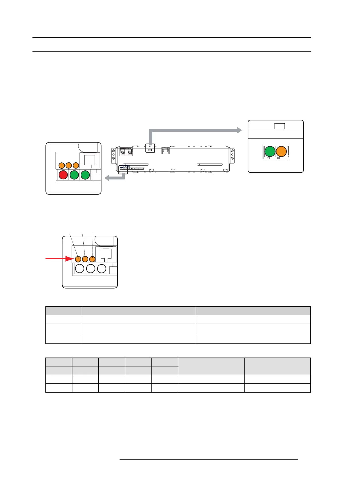
Status LED’s on LPS unit
The L PS module contains in total 8 s tatus LEDs. Four orange, three green and one red L ED.
The orange LED “LVPS OK” lights up immediately after the projector is switched on. At the same time, the heartbeat LED starts
blinking. All other status LEDs o f the LPS unit remain off. T his is the standby status of the LPS unit. Once the command is sent
to the LPS units to start up the projection lamp , the green LEDs are lighting up one after the other. Firs t the green LED “PFC OK”,
then the g reen LED “LP S O K” and finally, when the lamp is ignited, the g reen LED “LA MP ON”. The right or ange of the upper row
blinks. This is the heartbeat signal
The red LE D “ ERR” remains off unles s an error is d etected inside the LPS unit or when the LPS unit are ordered to shutdown due
to a malfunction somewhere else inside the projector.
LAMP ON / LVPS OK
ERR PFC
OK
LPS
OK
Image 17-2
LED indications
Diagnostic
About the orange LEDs next to the CT RL connectors:
ERR PFC
OK
LPS
OK
A
B
C
Image 17-3
LED A and B are only for internal use. LED C is the heartbeat LED.
Orange LED C Diagnostic s Action
Blinking Normal operation
-
OFF 12 V from backplane via C TR L IN not available on LPS
unit
Check 12V out on backplane.
ON 12 V from backplane available. Replace the LPS module.
About the diagnostic LEDs, ERR, PFC, LPS, Lam p ON and LVPS.
Orange Green Green Grreen Red
LVPS OK PFC OK LPS OK LAMP OK ERR
Diagnostic Action
OFF OFF OFF OFF OFF No input voltage. Switch on the projector.
ON OFF OFF OFF O F F Standby modus of LP S unit.
—
R5905043 DP2K-12C/11CX 19/02/2018 285
 Loading...


