17
Workshop Manual
Smart Tachograph EFAS-4.10/4.11
Table 8 — Pin assignment plug connector C
Contact Direction Function Comment Cable
cross-section
C1 n/a - - - Not used
C2 n/a - - - Not used
C3
5
In y Engine speed signal
y Input signal for second
motion source with
pulse output
y Digital input for engine-speed sensor
y Digital input for a pulse signal with frequency pro-
portional to speed
0.35 - 1 mm
2
C4 n/a - - - Not used
C5 Bi CAN_H (C) High-signal CAN bus C, 0.35 - 1 mm
2
C6 - CAN_GND (C) Ground CAN bus C 0.35 - 1 mm
2
C7 Bi CAN_L (C) Low-signal CAN bus C 0.35 - 1 mm
2
C8 - CAN (C) 120 CAN C terminator when connected to C7 0.35 - 1 mm
2
Table 9 — Pin assignment plug connector D
Contact Direction Function Comment Cable
cross-section
D1 In Status signal D1 Digital input e.g. temperature warning or red light 0.35 - 1 mm
2
D2 In Status signal D2 Digital input e.g. temperature warning or red light 0.35 - 1 mm
2
D3
5
n/a - - - Not used
D4
5
Out Warning signal Digital output for external optical alarm e.g. EFAS
announces malfunction to the “Combi” instrument
0.35 - 1 mm
2
D5
5
n/a - - - Not Used
D6
5
Out Speed signal
Special functions possible
Digital pulse output, e.g. for speedometer D6.
Requires Pull-up resistor 10 kOhm to A1 (battery +) for
correct function.
0.35 - 1 mm
2
D7
5
Bi K-line speedometer
(diagnostic interface)
Serial communication interface, e.g. for K-line
Voltage level identical to operating voltage
0.35 - 1 mm
2
D8 Out Serial interface
(diagnostic, FMS)
Serial communication interface for diagnosis or as an
information interface D7=D8 dierent voltage levels
Voltage level is selectable to operating voltage or 10 V
0.35 - 1 mm
2
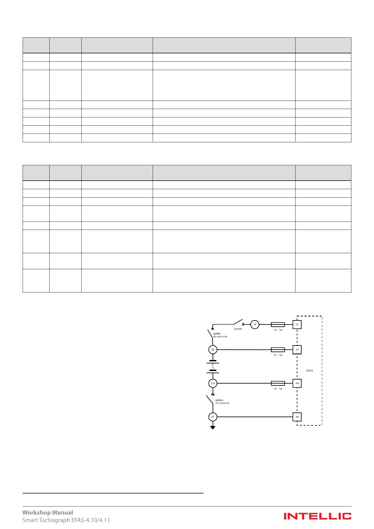
6.2.2.1 Protection of positive and negative pole
Protection without or with battery master switch at positive pole:
y A1, A2 min. 1 A / max. 5 A
y A3 min. 3 A / max. 5 A
y A5, A6 directly to the vehicle chassis
Protection with battery master switch at negative pole:
y A1, A2 min. 1 A / max. 5 A
y A3 min. 3 A / max. 5 A
y A5 min. current limit or fuse 1 A, max. 5 A
y A6 directly to the vehicle chassis
5 In the hardware of EFAS-4.10 this connection is internally unconnected
Figure 10 — Fuse protection in plus and minus branch

 Loading...