86
Workshop Manual
Smart Tachograph EFAS-4.10/4.11
The source can be congured with the EFAS Service Tool or a suitable testing / calibration device. In addition, at source C3, it is
necessary to set a parameter - the so-called n-factor - with which EFAS can calculate an engine speed from the pulse frequency.
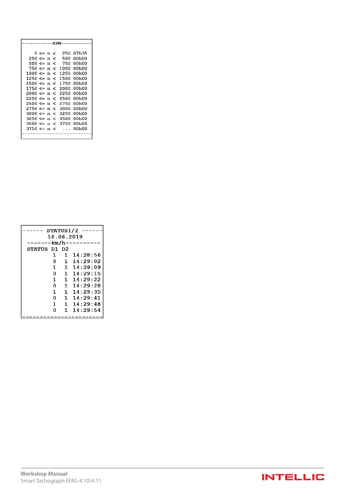
Figure 69 — Engine speed log
Data recording occurs in a similar manner to the recording of speed (v-prole). Again, a maximum of 16 groups (engine speed
ranges) are possible, with freely denable limits, within which the durations are recorded in hours and minutes.
14.3 Logging the two status inputs D1 and D2
The following diagram shows a log printout for the two digital status inputs D1 and D2.
At the tachograph’s D plug connector, the two connectors D1 and D2 are both connected as input. Every status change at these
connectors is logged with a time-stamp, which comprises the date and time to the nearest second.
Figure 70 — Log printout of the two status inputs
Signal changes at the status inputs D1 and D2 are recorded independently of the ignition signal. The minimum pulse length
which is interpreted as a change is 100 ms. If several changes occur per second, the signal state that is detected most often per
second is taken for this second and stored.
An identier for the meaning of inputs D1 and D2 can be programmed into the EFAS with the EFAS Service Tool or a suitable
testing / calibration device. This identier is specied in the printout.
 Loading...