48
Workshop Manual
Smart Tachograph EFAS-4.10/4.11
10.6.7 Testing the warning lamp and the acoustic alarm
This test checks that the warning light in the front module and the integrated acoustic alarm are functioning. The test activates
the warning light and acoustic alarm for one second. Then both signal components are restored to their status prior to the test.
Note In this test there is no additional text visible on the display unit of the EFAS.
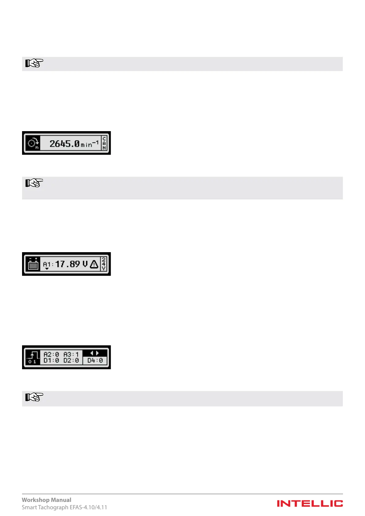
10.6.8 Testing the engine-speed signal source
Using this test, one can check whether the speed recording has been congured correctly. A test of the engine-speed detection
is necessary if the EFAS is to record engine speed. The source of the recorded engine speed is either the pulse input (Pin C3) on
the vehicle connector socket or the CAN bus. The source can be set with the help of a parameter using a suitable test instrument
or the EFAS Service Tool. After calling up the test-function the source of the speed signal is displayed on the right side. When
recording pulses via the pulse input, the parameter for the speed constant (n factor) must be set accordingly.
Figure 59 — Testing the engine-speed signal source
Note Also observe the parameter setting for the engine-speed interval limits. The engine-speed interval limits can
be congured either with an appropriate test instrument or using the EFAS Service Tool. For more detailed
information see Chapter 14 and especially 14.2.
10.6.9 Testing the on-board power supply
This test function is used to check the on-board power supply, which is available at pin A1 of the connector socket in the EFAS.
If the voltage measured is beyond the specied limits of the operating voltage for the tachograph, then the fault condition is
displayed additionally using a ashing warning symbol on the right side. At the right edge the nominal voltage of the vehicle is
displayed as detected by EFAS or as entered manually.
Figure 60 — Display of the on-board power supply
10.6.10 Testing for digital inputs/outputs at the connector panel
This test function is used to inspect the digital inputs and outputs at the connector socket of the EFAS. The wiring at the con-
nector socket and the connection to the devices attached can be checked in this manner. The logical signal level (value “0” or “1”)
is displayed for the inputs light/lighting (pin A2), for the ignition signal (pin A3), for the status inputs (pins D1 and D2) and for
the warning signal output (pin D4).
Figure 61 — Inputs / Outputs
Note When the ignition signal (A3) is switched on, the test terminates after a short while and must then be restarted
with the ignition switched on.
The signal at the warning output (pin D4) can be set to the value “0” or “1” using the arrow keys on the keyboard. After the test
has ended, the previous state of the warning output is restored.
10.6.11 Testing the rotational speed of the output shaft
This test function is used to verify the calculated value of the rotational speed of the output shaft. The value displayed is based
on the speed pulses from the motion sensor and the parameter value set to calculate the output shaft speed.
 Loading...