CHAPTER 4 DISASSEMBLY AND RE-ASSEMBLY
Confidential
4-22
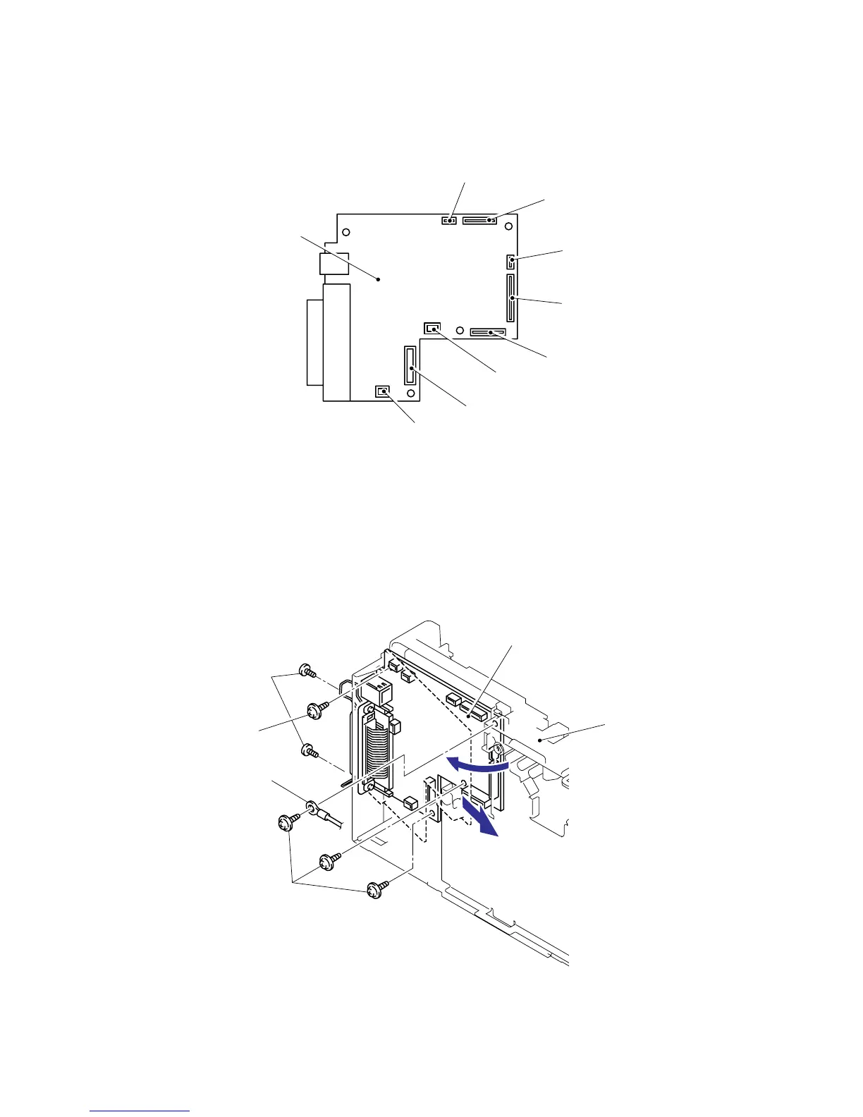
3.13 Main PCB
<HL-2030/2040>
(1) Disconnect the eight connectors from the main PCB.
Fig. 4-35
(2) Remove the four cup S M3x6 taptite screws and FG harness ASSY 6.
(3) Remove the two flat S M3x8 taptite screws.
(4) Remove the main PCB from main frame L.
NOTE:
When replacing the main PCB, refer to ‘ADJUSTMENTS AND UPDATING OF
SETTINGS, REQUIRED AFTER PARTS REPLACEMENT’ in Chapter 6.
Fig. 4-36
LD harness 5P
Taptite flat S M3x8
Taptite cup S M3x6
Main PCB
Main frame L
2
Polygon motor connector
(LV harness ASSY)
Panel PCB connector
HVPS connector
(It has been taken back.)
Thermistor relay harness
Main motor connector
Main PCB
Taptite cup S M3x6
LVPS connector
Fan motor 60 unit connector
1
FG harness ASSY 6
 Loading...