6–17
Chapter 6: PLC Communications
6
EA1-MG6-USER-M Hardware User Manual, 1st Ed. Rev C, 09/10
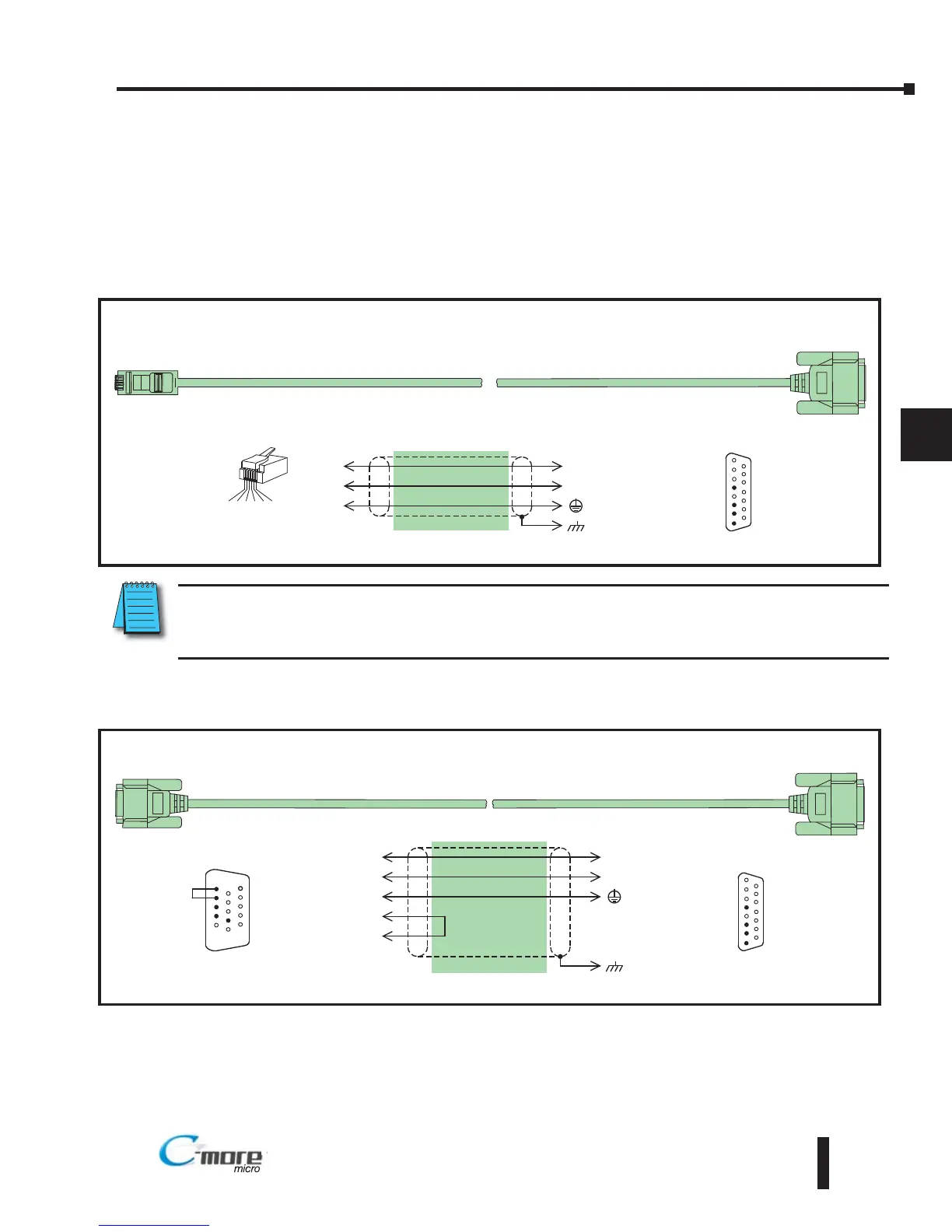
Cables from AutomationDirect – Wiring Diagrams
The following series of wiring diagrams show the connectors and wiring details for the
communication cables that are used between the C-more Micro-Graphic panels and various
PLCs. Part numbers are included with the pre-made cables that can be purchased from
AutomationDirect. The information presented will allow the user to construct their own cables
if so desired.
CLICK & Direct LOGIC:
Note: Only one C-more Micro-Graphic panel can be powered by an AutomationDirect PLC. If connecting
C-more Micro-Graphic panels to more than one port on and AutomationDirect PLC, the additional panel
must use an external power supply.
Direct LOGIC:
Productivity Series, CLICK and Direct
Logic PLC RJ12 port:
DL05, DL06, DL105, DL205, DL350, DL450, H2-WINPLC
RS-232C (p/n EA-2CBL)
8 = do not use
7 = do not use
6 = do not use
5 = Logic GND
4 = do not use
3 = RXD (232C)
2 = TXD (232C)
1 = Frame GND
To PLC
RJ12 Port
4
15 = do not use
14 = do not use
13 = do not use
12 = do not use
11 = do not use
10 = do not use
9 = do not use
1
15
1 = Sig GND
2 = do not use
3 = RXD
4 = TXD
5 = do not use
6 = do not use
15-pin
D-sub
(male)
1 2 3 4 5 6
3
1
TXD
RXD
GND
3
2
5
1
RXD
TXD
shield
RJ12 6-pin
Phone Plug
(6P6C)
Wiring Diagram
Note: Use the above wiring diagram if you need to make your own cable. We recommend using 22 AWG shielded cable.
To C-more Micro-Graphic
Serial Port2
Direct
Logic PLC (VGA style) 15-pin HD port:
D2-250, D2-250-1, D2-260, DL06
RS-232C (p/n EA-2CBL-1)
8 = do not use
7 = do not use
6 = donot use
5 = Logic GND
4 = do not use
3 = RXD (232C)
2 = TXD (232C)
1 = Frame GND
To PLC
15-Pin HD Port
2
15 = do not use
14 = do not use
13 = do not use
12 = do not use
11 = do not use
10 = do not use
9 = do not use
1
15
15-pin
D-sub
(male)
3
7
TXD
RXD
GND
3
2
5
1
RXD
TXD
shield
15-pin
HD D-sub
(male)
Wiring Diagram
Note: Use the above wiring diagram if you need to make your own cable. We recommend using 22 AWG shielded cable.
8 = do not use
7 = Sig GND
6 = do not use
5 = CTS
4 = RTS
3 = RXD
2 = TXD
1 = +5 VDC - N/C
15 = do not use
14 = do not use
13 = do not use
12 = do not use
11 = do not use
10 = do not use
9 = do not use
1
6
15
4
RTS
5
CTS
HD = High Density
To C-more Micro-Graphic
Serial Port2
 Loading...