6–11
Chapter 6: PLC Communications
6
DirectLOGIC DL305 PLCs and D3-DCM Module
Panel Powered via external power supply, Port1 or Port2 Communications
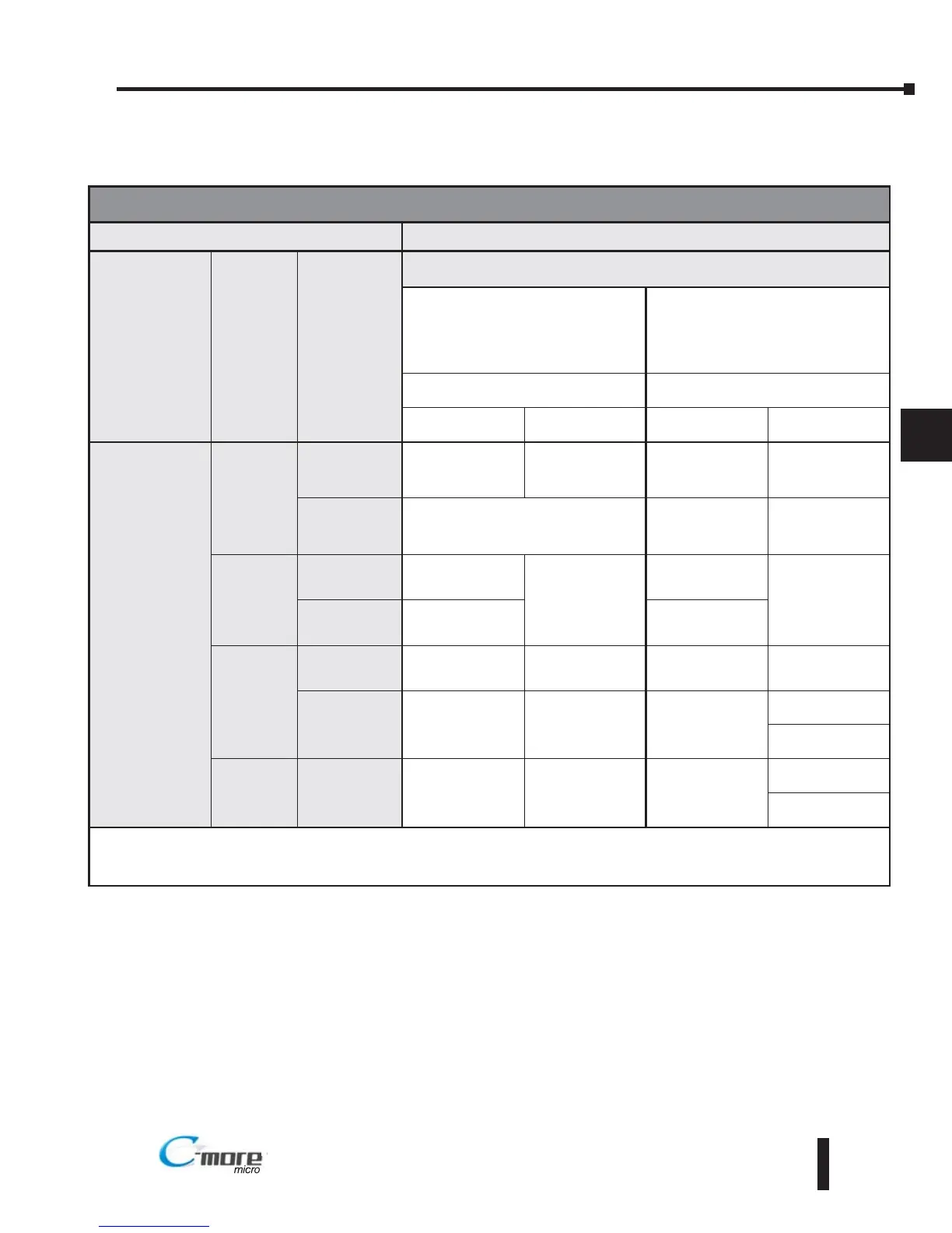
PLC Compatibility & Connection Chart
PLC C-more Micro-Graphic Panel
Family CPU
PLC Port &
Type
Panel to PLC Cabling Components Required for
Specific Port and Protocol being used.
*PLC Port Powered
or
External DC Power Supply
External DC Power Supply
Using panel’s RJ12 Port1
Using panel’s Port2
DB 15-pin - female
Protocol(s)
Supported
Components &
Network Type
Protocol(s)
Supported
Components &
Network Type
Direct
LOGIC
DL305
D3-330 or
D3-340
D3-232-DCU
DB 25 pin
(female)
Direct
NET
** See Diagram 3
RS-232
Direct
NET
** See Diagram 3
RS-232
D3-422-DCU
DB 25 pin
(female)
Not Possible
Direct
NET
** See Diagram 6
RS-422
D3-340
Port 1
RJ11 - 4 pin
Direct
NET
OP-3CBL-1
RS-232
Direct
NET
EA-3CBL
RS-232
Port 2
RJ11 - 4 pin
Direct
NET,
Modbus RTU
Direct
NET,
Modbus RTU
D3-350
Port 1
RJ12 - 6 pin
K-sequence,
Direct
NET
DV-1000CBL*
RS-232
K-sequence,
Direct
NET
EA-2CBL
RS-232
Port 2
DB 25 pin
(female)
K-sequence,
Direct
NET,
Modbus RTU
** See Diagram 3
RS-232
K-sequence,
Direct
NET,
Modbus RTU
EA-4CBL-2
RS-232
** See Diagram 4
RS-422
D3-DCM
D3-350 only
Port 1
DB 25 pin
(female)
K-sequence,
Direct
NET,
Modbus RTU
** See Diagram 3
RS-232
Direct
NET
EA-4CBL-2
RS-232
** See Diagram 6
RS-422
* Note: The PLC can provide 5 VDC through this cable. No external 12-24 VDC souce is required, however, screen
brightness is diminished and the alarm beep will not function.
** Note: Wiring Diagrams for user constructed cables start on page 6-26.
EA1-MG6-USER-M Hardware User Manual, 1st Ed. Rev C, 09/10
 Loading...