EA1-MG6-USER-M Hardware User Manual, 1st Ed. Rev C, 09/10
1–13
Chapter 1: Getting Started
1
Step 7 – Providing Power to the C-more 6” Micro-Graphic Panel
Power can be supplied to the C-more Micro-Graphic panel in one of three different ways.
1.) During operation, the panel functions in High-Power Mode when powered by a minimum 1 Amp
12 - 24 VDC power source. Recommended power supplies are AutomationDirect part number
PSP24-024S or PSP24-024C.
2.) The C-more Micro-Graphic panel is powered during programming from the PC through the USB
to RS-232 Programming Cable Assembly, EA-MG-PGM-CBL. The panel will operate in Low-
power mode when powered by the PC and result in a dim screen.
3.) Optionally, the C-more Micro-Graphic panel can function in Low-Power Mode powered from most
AutomationDirect PLC’s RJ12 serial communications port. Use a DV-1000CBL communications
cable, or a DV-1000CBL communications cable with a FA-15HD 15-pin HD DSub/RJ12 Adapter
connected to most AutomationDirect PLC’s 15-pin HD communications port (DL06, D2-250-1
& D2-260) PLCs for Low-Power operation. See Chapter 6: PLC Communications for additional
details. The panel will operate in low-power mode when powered by the PC.
Power Supplied to Panel through Cable from CLICK and Direct
Logic PLC RJ12 port:
DL05, DL105, DL205, DL350, DL450, H2-WINPLC
RS-232C (p/n DV-1000CBL)
To PLC
RJ12 Port
To C more
Micro Graphic
Serial Port1
6
4
GND
TXD
1
3
GND
Wiring Diagram
3
RXD
2
+5 V
1 Sig GND
2 not used
3 RXD
4 TXD
5 +5 VDC
6 Sig GND
1 2 3 4 5 6
RJ12 6 pin
Phone Plug
(6P6C)
1
GND
6
GND
1 2 3 4 5 6
RJ12 6 pin
Phone Plug
(6P6C)
1 S g GND
2 +5 VDC
3 RXD
4 TXD
5 not used
6 S g GND
4
5
RXD
TXD
+5 V
10 feet [3.0 m] Maximum
L T D
*Panel Powered from
AutomationDirect PLC via
Communications Cable
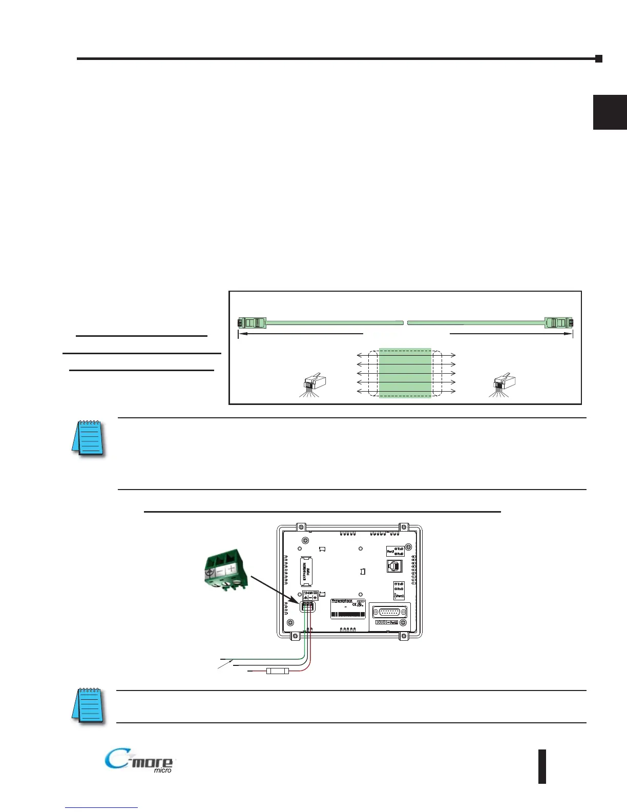
Panel Powered from a DC Power Source - Wiring Diagram
NOTE: Recommended DC power supply to power the C-more Micro Graphic Panel, AutomationDirect Part No.
PSP24-024S or PSP24-024C.
NOTE: When the 6” panel is powered through Port1 from a connected PLC or PC, the screen brightness is
diminished because the panel is running in Low-Power Mode. For full brightness, connect an external
12-24 VDC power source to the panel’s power connection. Low-Power Mode is intended for initial
programming. For full brightness, connect an external 12-24 VDC power source when the panel is installed
in its application.
 Loading...