EA1-MG6-USER-M Hardware User Manual, 1st Ed. Rev C, 09/10
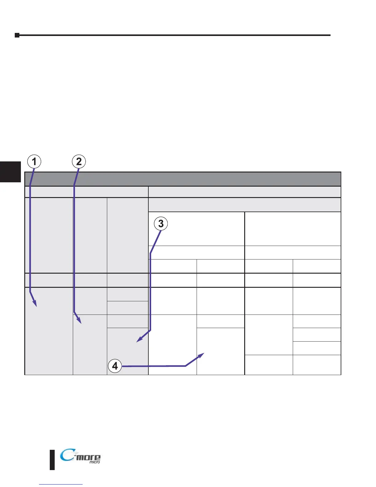
How to use the PLC Compatibility and Connection Charts
1.) Find the PLC Family being used.
2.) Find the particular PLC model in the PLC family.
3.) Find the PLC communications port you will be connecting to the C-more Micro-Graphic
panel.
4.) Read across the chart to determine if the C-mor e Micro-Graphic panel’s Port1 and / or Port2
can be used and then determine the cable and other components, manufactured or user
constructed, are required.
Example:
PLC Compatibility & Connection Chart
PLC
C-more
Micro-Graphic Panel
Family CPU
PLC Port &
Type
Panel to PLC Cabling Components Required for
Specific Port and Protocol being used.
**PLC Port Powered
or
External DC Power Supply
External DC Power Supply
Using panel’s RJ12 Port1
Using panel’s Port2
DB 15-pin - female
Protocol(s)
Supported
Components &
Network Type
Protocol(s)
Supported
Components &
Network Type
CLICK
all versions
Port 1
RJ12 - 6 pin
AutomationDirect
Modbus (CLICK)
DV-1000CBL*
RS-232
AutomationDirect
Modbus (CLICK)
EA-2CBL
RS-232
Direct
LOGIC
DL05
all versions
Port 1
RJ12 - 6 pin
K-sequence,
Direct
NET,
Modbus RTU
DV-1000CBL*
RS-232
K-sequence,
Direct
NET,
Modbus RTU
EA-2CBL
RS-232
Port 2
RJ12 - 6 pin
D0-DCM
Port 1
RJ12 - 6 pin
K-sequence,
Direct
NET,
Modbus RTU
DV-1000CBL*
RS-232
K-sequence,
Direct
NET,
Modbus RTU
EA-2CBL
RS-232
Port 2
DB15HD
(female)
DV-1000CBL*
+ FA-15HD
RS-232
EA-2CBL-1
RS-232
** See Diagram 1
RS-422
Modbus RTU
** See Diagram 2
RS-485
Modbus only
 Loading...