EA1-MG6-USER-M Hardware User Manual, 1st Ed. Rev C, 09/10
Chapter 1: Getting Started
1
1–12
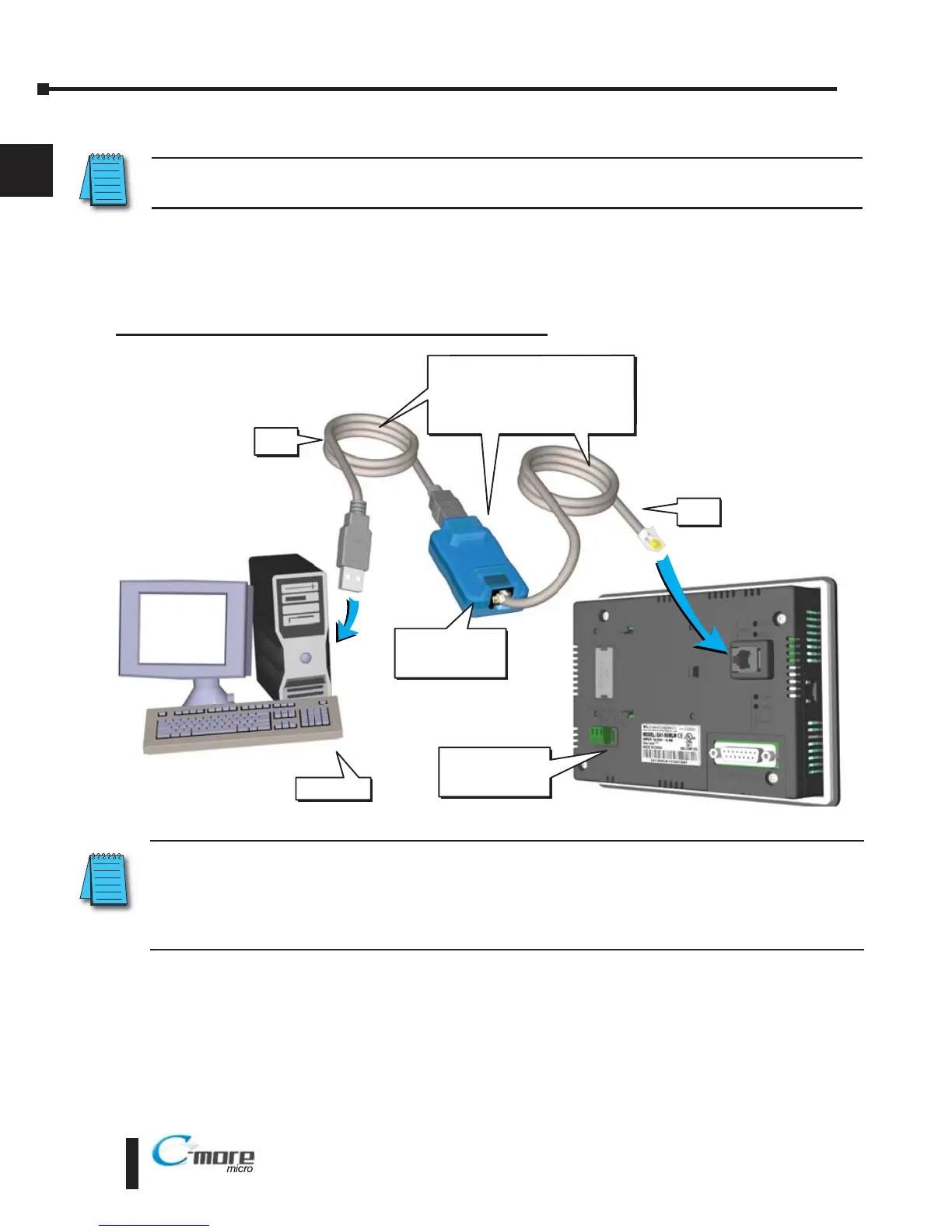
Step 6 – Connect C-more 6” Micro-Graphic Panel to Computer
NOTE: Install C-more Micro-Graphic Programming software before connecting the panel to the PC to ensure
the panel drivers install correctly.
Use an EA-MG-PGM-CBL, USB to RS-232 Programming Cable Assembly, from an USB
port type A on the project development PC, through the supplied converter, to the RJ12 RS-
232 programming/PLC serial communications port on the C-more Micro-Graphic panel as
shown below.
C-more 6 inch
Micro Graphic
Panel
USB
Cable
User PC
Serial
Cable
PC to Panel Programming
Cable Assembly
(Includes serial & USB cables)
EA MG PGM CBL
USB to RS232
Converter
USB to RS-232 Programming Cable Assembly
NOTE: When the panel is powered through Port1 from a connected PLC or PC, the screen brightness is
diminished because the panel is running in Low-Power Mode. For full brightness, connect an external
12-24 VDC power source to the panel’s power connection. Low-Power Mode is intended for initial
programming. For full brightness, connect an external 12-24 VDC power source when the panel is installed
in its application.
 Loading...