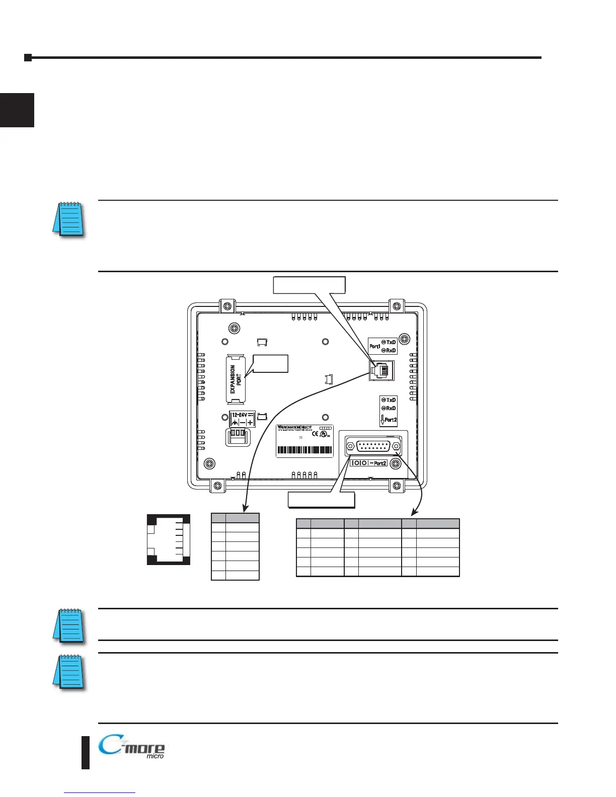
Step 3 – Become Familiar with Available Communication Ports
The C-more 6” Micro-Graphic panel includes a built-in RS-232 serial communications port
designated as Port1. This port uses an RJ12 type telephone jack to make connections to either
the EA-MG-PGM-CBL programming cable assembly or a communications cable, such as an
EA-2CBL, to interface with a PLC or controller. The panel can receive power through this port
from the serial communications port on AutomationDirect CLICK™ and select
Direct LOGIC PLCs. The other serial communications port designated as Port2 is a 15-pin D-
sub connector that supports RS-232, RS-485 and RS-422.
NOTE: When the 6” panel is powered through Port1 from a connected PLC or PC, the screen brightness is
diminished because the panel is running in Low-Power Mode. For full brightness, connect an external
12-24 VDC power source to the panel’s power connection. Low-Power Mode is intended for initial
programming. For full brightness, connect an external 12-24 VDC power source when the panel is installed
in its application.
NOTE: See Chapter 2: Specifications and Chapter 6: PLC Communications for additional details on the
available communication ports, protocols and cables.
NOTE: The panel has a built-in RJ12 serial communications port (Port1 - RS-232) and a built in 15-pin serial
communications port (Port2 - RS-232/422/485). Only one of the ports can be used with a connected PLC.
The programming software allows the user to select either Port1 or Port2 under the Panel Manager dialog
box. When using Port2 to communicate with the connected PLC, Port1 can still be used with the EA-MG-
PGM-CBL Software Programming Cable Assembly to transfer projects between the PC and panel.
EA1-MG6-USER-M Hardware User Manual, 1st Ed. Rev C, 09/10
1–8
Chapter 1: Getting Started
1
IS EDIS ED
7M177M17
Date code:** *Date code:** *
5432
R01.R01.
MADE IN CH NAMADE IN CH NA
EA1-S6MLW + ser al numberEA1-S6MLW + ser al number
MODEL:EA1 S6MLWMODEL:EA1 S6MLW
NPUT:12 24V 6 5WNPUT:12 24V 6 5W
ND.CONTEQ.ND.CONTEQ.
 Loading...