7 . ACCESSORIES AND OPTIONS
7.11
Challenger MT500B EU
7
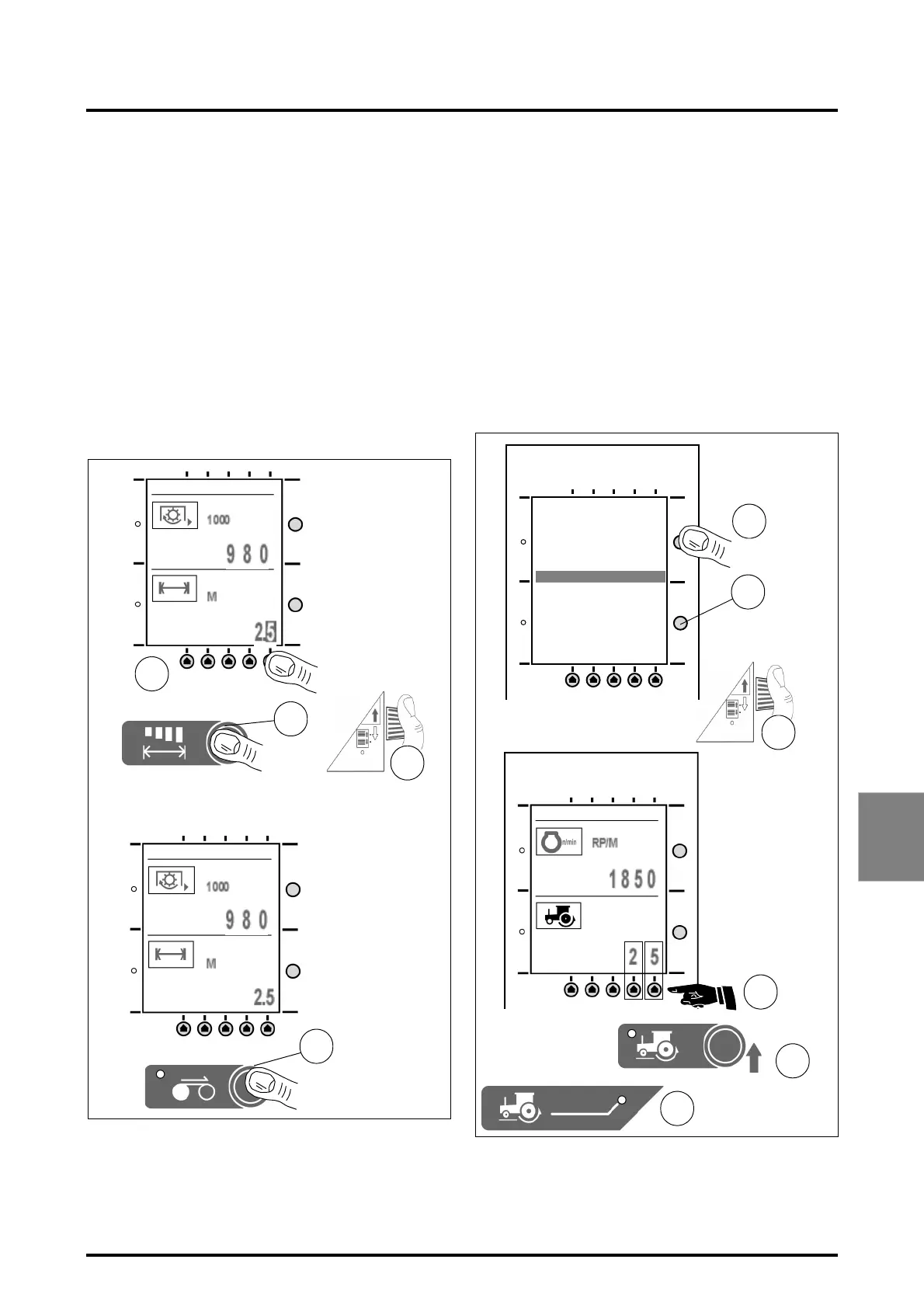
Working position
This operating mode takes three parameters into account:
1. The PTO speed in ON/OFF position,
2. The linkage (low position) ON/OFF,
3. The towed implement (through the auxiliary socket
located in the cab).
Application:
Select the working width of the implement to be used by
pressing the key ref. 7 (Fig. 8), modify the digits by pressing
the corresponding keys ref. 6, then turn the knob 14 to dis-
play the new values, and press the key ref. 7 again to return
to the previous screen.
NOTE: The display of the work function has priority
whenever the key is pressed.
• Select the work function ref. 11; when the display
appears, work can start.
7.2.7 - Wheel slip control
(Fig. 9)
Setting the maximum slip limit
• Select -WHEEL SLIP LIMIT- in the function menu. Press
keys ref. 6 to enter the value.
• When the wheel slip control ref. 12 is on, the system
continuously compares the real wheel slip rate with the
limit set by the operator.
As long as wheel slip is lower than the set limit, normal
operation is possible. If the level exceeds the previously
set limit, the system lifts the implement until wheel slip
returns to an allowable level, and the control indicator
light ref.13 comes on. The system also responds in this
manner when the operator adjusts height / depth on the
linkage console.
14
Fig. 8
7
11
6
V919
V919
4. PLOUGH.
4. PLOUGH.
14
2
3
6
12
13
ENGINE RPM
PTO 540 RPM
PTO 1000 RPM
FWD SPEED
WHEEL SLIP
WHEEL SLIP LIMIT
AREA/HOUR
FUEL/HOUR
FUEL/AREA
COST/AREA
FUEL USED
AREA WORKED
Fig. 9
V916
V916
V916
4. PLOUGH.
 Loading...