7 . ACCESSORIES AND OPTIONS
7.83
Challenger MT500B EU
7
Furrow end:
Actuate the rear linkage lifting control as soon as the first
share is positioned on mark Y. At the same time, the
plough depth wheel makes a half turn (64). As soon as dis-
tance X has been covered, the depth wheel lifts to its high
position (65).
IMPORTANT: If the linkage high and low stops are mod-
ified during work, they are not stored in the
DATATRONIC active memory. To memorise them, see
paragraph 7.8.3.2. (Memorising high and low linkage
positions).
NOTE: For pointed fields, the POINTS menu must be
used to optimise the operation of the DUAL CONTROL.
This allows the tractor to make straight furrow starts
and ends, whatever the field shape. To make these
adjustments, see section 7.8.5 (POINTS menu).
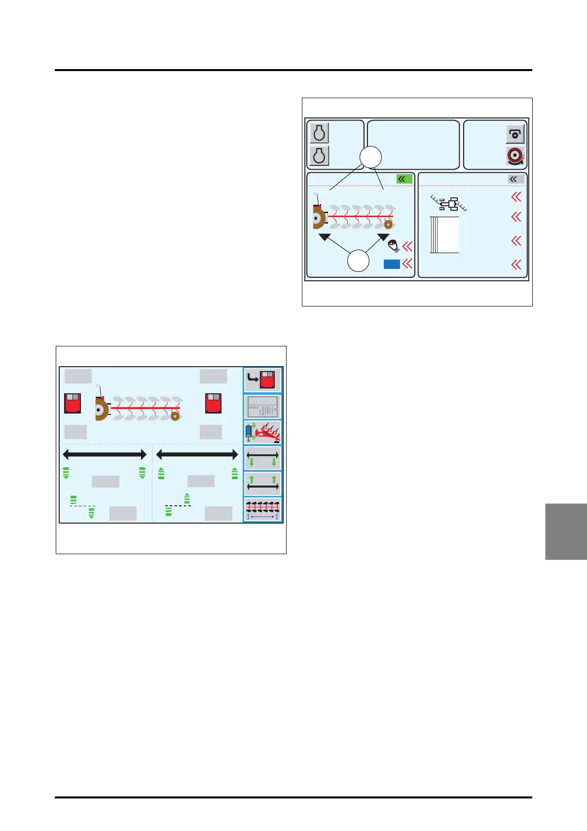
Displaying parameters:
During work either the Settings window (Fig. 202), or the
Work window (Fig. 203) can be displayed.
Description (Fig. 202):
As the plough position changes, the linkage and depth
wheel high and low position values vary accordingly.
The values in the grey boxes are memorised and fixed.
Description (Fig. 203):
To display this window, press the key
«
2
when the win-
dow (Fig. 202) is open.
Left-hand part of the window:
The linkage and depth wheel position values (66) are the
active values.
The symbols under the linkage and depth wheel (67) in-
dicate their control status.
Right-hand part of the window:
See paragraph 7.8.6 (POINTS menu).
7.14 -
TRAILED IMPLEMENT CONTROL (T. I. C.)
This menu controls the trailed implements hitched to the
swinging drawbar or lift arms (linkage is fixed). In work
mode, wheel slip, implement depth and draft applied to the
lift arms (when an implement is hitched to the lift arms) are
analysed by the linkage calculator, which varies the imple-
ment working height accordingly.
The information required for system operation is acquired
by 4 sensors :
- two draft sensor on the lift arms,
- one trailed implement position sensor,
- one ground speed radar.
79%68%
85%
27%
27%
4.5
59%
59%
6.0
1920
42.0
68% 79%
27% 32%
4.5
85%
6.0
Z3A-983-08-04-B
Fig. 202
m
m
m
m
A
B
1000
2000
790
5.3
10% M
5%
2
2000
27 % 32%
ON
1
0.0
0.0
Reset
Syncr
Z3A-984-08-04-B
Fig. 203
REAR DUAL CTRL POINTS
m
m
RPM
KPH
66
67
 Loading...