7 . ACCESSORIES AND OPTIONS
7.32
Challenger MT500B EU
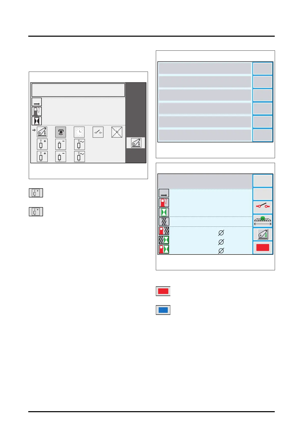
On b/w screens:
The principle is identical, except that the spool valve icons
are identified by numbers (Fig. 32).
To select an event, turn the encoder to position the marker
opposite the required icon. Then validate by pressing the
encoder. The window (Fig. 30) is displayed again with the
selected icon.
7.8.8 - Activating a memory
• When the window (Fig. 33) is open, select a memory by
pressing the corresponding key. Example: the DISC
TILLER memory by pressing the key
«
3
. This implement
window (Fig. 34) is displayed.
• Press the key
«
6
to activate or deactivate the memory:
NOTE: To return to the previous menu, press the ESC
key.
When a memory is active, all parameters defined and
measured shall be stored in this memory:
- memory name
- event used to perform counting,
- total fuel consumption,
- area worked,
- hours worked,
- distance,
- implement width,
- headland sequence (see HEADLAND application),
Icons with number 1 displayed correspond to the
red spool valve (located on the Joystick)
Icons with number 2 displayed correspond to the
green spool valve (located on the Joystick)
3
0
0:00
0.0
0
0.0
0:00
111
222
Z3A-1338-12-04
Fig. 32
DISC TILLER
KM
1
2
Inactive memory
Active memory
1
5
4
3
2
6
DUAL CTRL AR
DUAL CTRL AV
Z3A-894-08-04-B
Fig. 33
PLOUGH
SELF LOADING TRAILER
DISC TILLER
SUBSOILER
SPREADER
ROTARY HARROW
3
4.5
ABC...
OFF
=
=
=
Reset
0
0
0.0
0.0
0 000
0:00
0.0
0.0
0.0
0.0
0.0
0
0.0
0:00
Z3A-926-08-04-B
Fig. 34
DISC TILLER
KM
L/HA
HA/H
L/H
M
L
HA
H
M
OFF
ON
 Loading...