15-4
Catalyst 6500 Series Switch and Cisco 7600 Series Router Firewall Services Module Configuration Guide
OL-6392-01
Chapter 15 Using Failover
Understanding Failover
Module Placement
You can place the primary and secondary FWSMs within the same switch or in two separate switches.
The following sections describe each option:
• Intra-Chassis Failover, page 15-4
• Inter-Chassis Failover, page 15-4
Intra-Chassis Failover
If you install the secondary FWSM in the same switch as the primary FWSM, you protect against
module-level failure. To protect against switch-level failure, as well as module-level failure, see the
“Inter-Chassis Failover” section on page 15-4.
Even though both FWSMs are assigned the same VLANs, only the active module takes part in
networking. The standby module does not pass any traffic.
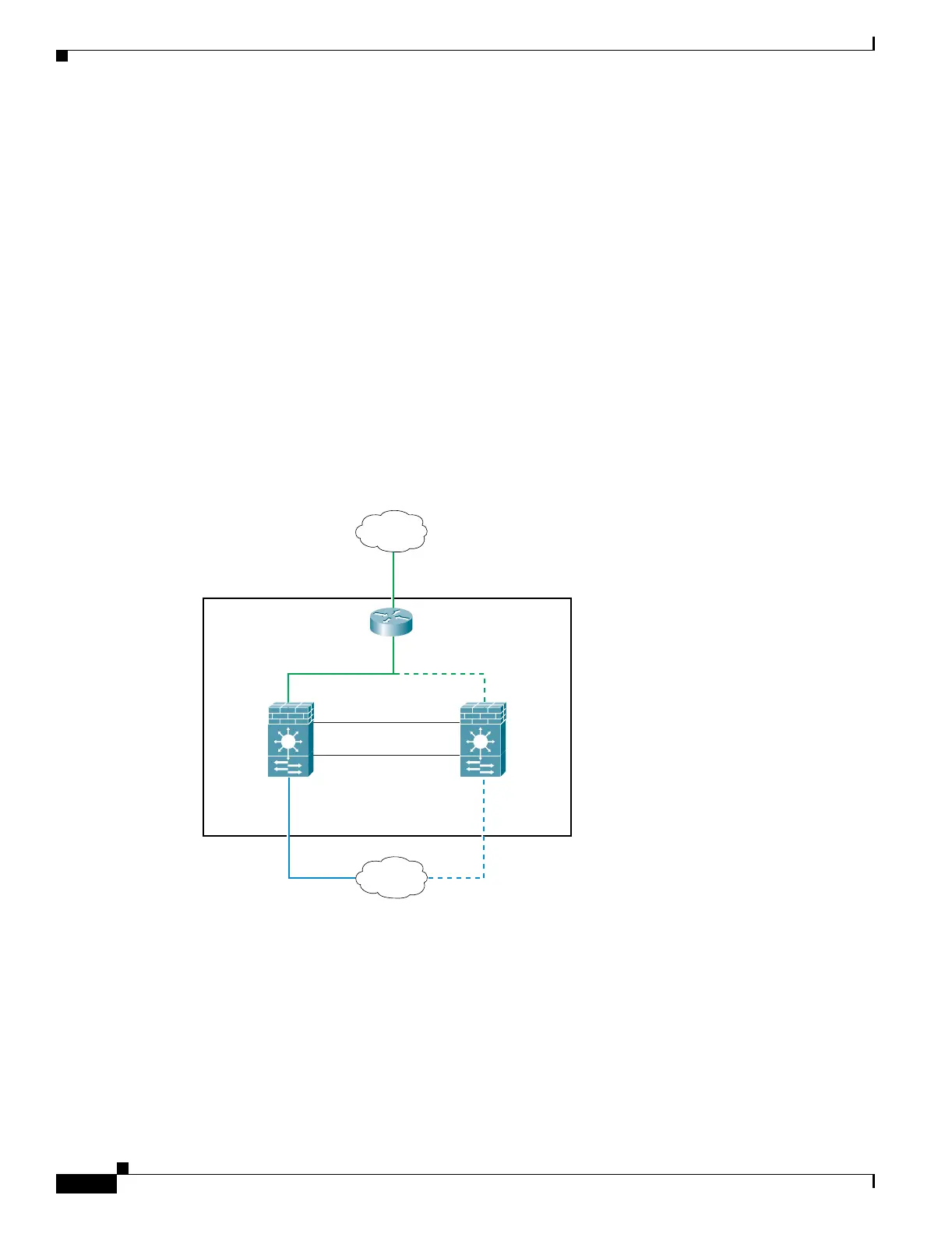
Figure 15-1 shows a typical intra-switch configuration.
Figure 15-1 Intra-Switch Failover
Inter-Chassis Failover
To protect against switch-level failure, you can install the secondary FWSM in a separate switch. The
FWSM does not coordinate failover directly with the switch, but it works harmoniously with the switch
failover operation. See the switch documentation to configure failover for the switch.
To accommodate the failover communications between the FWSMs, you must configure a trunk port
between the two switches that carries all the FWSM VLANs. Because this trunk also accommodates
FWSM traffic when a module fails, this trunk should be at least as large as the maximum amount of
Active
FWSM
VLAN 200
Switch
VLAN 100
VLAN 201
Standby
FWSM
Internet
State VLAN 11
Failover VLAN 10
Inside
104650
 Loading...


