B-6
Catalyst 6500 Series Switch and Cisco 7600 Series Router Firewall Services Module Configuration Guide
OL-6392-01
Appendix B Sample Configurations
Routed Mode Examples
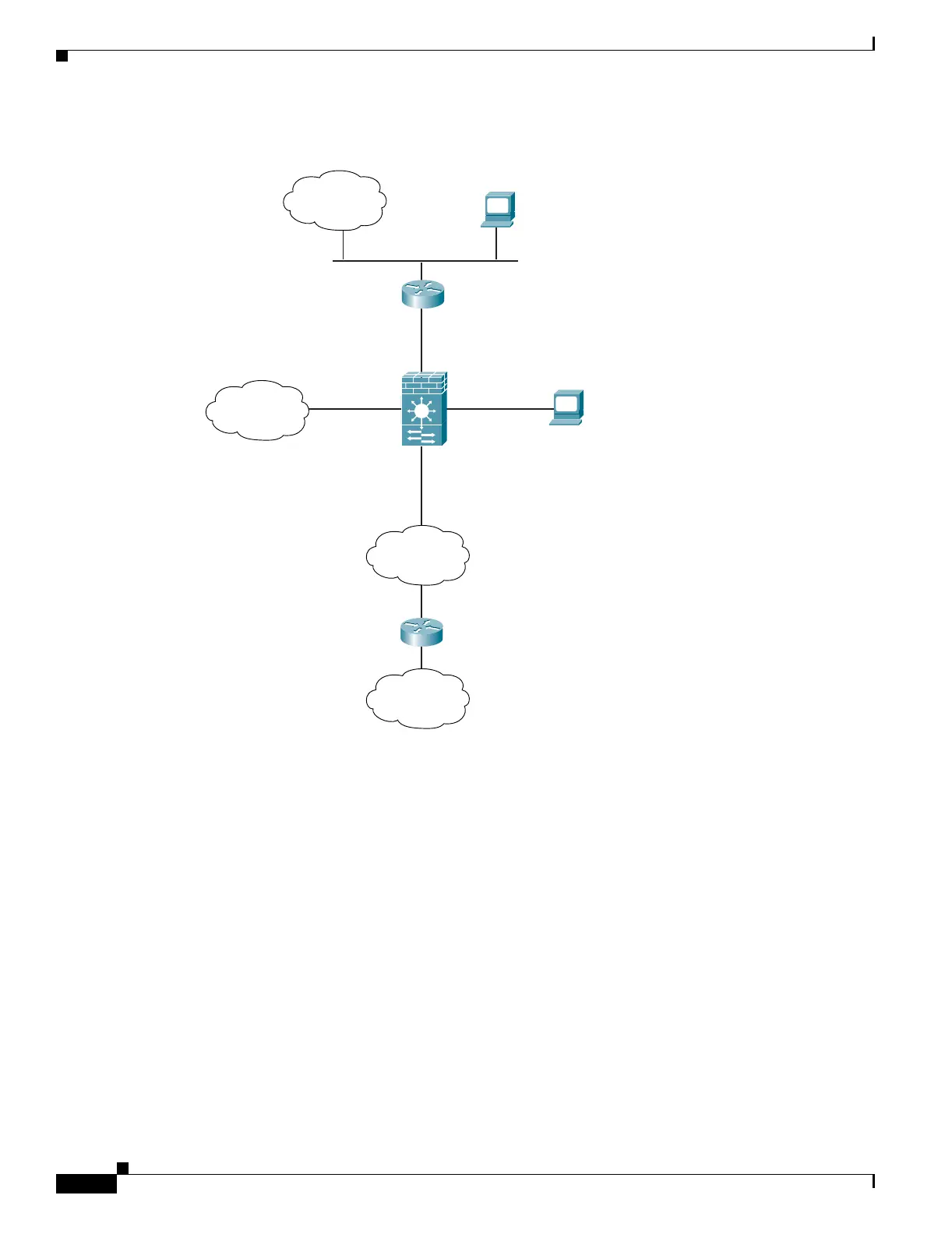
Figure B-2 Example 2
See the following sections for the configurations for this scenario:
• Example 2: FWSM Configuration, page B-6
• Example 2: Switch Configuration, page B-7
Example 2: FWSM Configuration
nameif vlan3 outside security0
nameif vlan4 dept2 security100
nameif vlan5 dept1 security100
nameif vlan10 dmz security50
passwd g00fba11
enable password gen1u$
hostname Buster
same-security-traffic permit inter-interface
ip address outside 209.165.201.3 255.255.255.224
ip address dept2 10.1.2.1 255.255.255.0
ip address dept2 10.1.1.1 255.255.255.0
ip address dmz 192.168.2.1 255.255.255.0
route outside 0 0 209.165.201.1 1
nat (dept1) 1 10.1.1.0 255.255.255.0
nat (dept2) 1 10.1.2.0 255.255.255.0
VLAN 10
DMZ
192.168.2.1
Syslog Server
192.168.2.2
Management Host
209.165.200.225
outside
209.165.201.3
VLAN 4
VLAN 5
VLAN 9
VLAN 3
MSFC
209.165.201.1
Internet
Department 2
Department 2
Network 2
Department 1
dept2
10.1.2.1
dept1
10.1.1.1
10.1.2.2
192.168.1.1
104646
 Loading...


