DESIGNER’S HANDBOOK 4189350049C EN Page 202 of 206
Please see chapter “PDO converter for azimuth/rudder” for detailed information on how to make this calibration
from menu.
4. If the commanded rudder (set point) needs adjustment, select the rudder set point from the “Adjust input”
menu. The calibrated data is shared on XDi-net.
5. Setup is completed.
*) If it is difficult to physically reach the rudder transmitter, the alignment can be made in the indicator itself via the
setup menu. The alignment will automatically be shared with all other XDi rudder indicators.
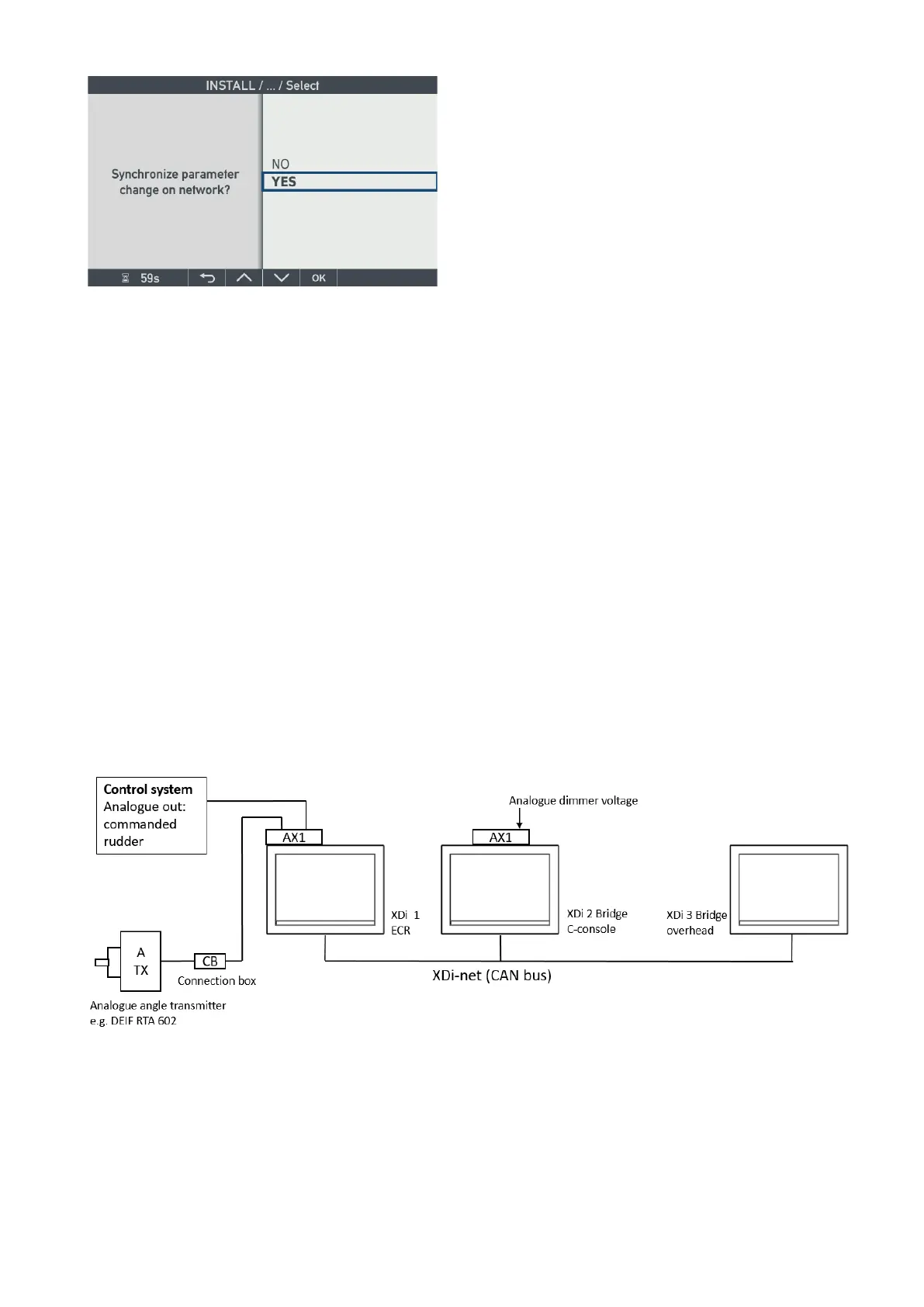
13.6 Application 6: XDi rudder system, analogue angle transmitter and XDi-
net
The system below is using an analogue 4-20 mA rudder transmitter (for example RTA 602) and three XDi units
using the DEIF Standard XDi Dual rudder library.
The indicators are presenting actual rudder angle and the commanded rudder angle.
(See DEIF standard XDi rudder libraries for indicator details).
13.6.1 System overview
Select a different NodeID for each of the 3 XDi indicators, and make sure that it is not already used by another
CAN device on the bus.

 Loading...
