By selecting from the standard virtual indicators and standard setup profiles, the system can be configured.
The system is similar to the system in APP.1, but the angle transmitter has analogue output.
13.6.2 Setup procedure:
When powered up the first time:
1. Follow the installation wizard to select can Node ID, Product profile (PP), Virtual indicator (VI) and setup
profile (VS) and finish the wizard on XDi 1, XDi 2 and XDi 3. (See selection in table.)
2. Follow the instructions for electric zero set and min/max adjust of the rudder angle transmitter.*)
3. If the min/max rudder angle is inaccurate, it may be due to mechanical inaccuracy or gearing between
rudder and transmitter. Open the installation menu on the XDi where the analogue input is connected,
select the “Adjust input” menu, and then the rudder angle input (analogue input adjust). Use the setup
menu to calibrate the zero point and endpoints one by one. This XDi shares angle data on XDi-net, so you
should select NO to synchronise parameters; it has no effect in this case.
See chapter “AX1 analogue input – azimuth/rudder set point” for a detailed description on how to make this
calibration from menu.
4. If the commanded rudder (set point) needs adjustment, select the rudder set point from the “Adjust input”
menu and make the adjustments; again, the calibrated data is shared on XDi-net.
5. Setup is completed.
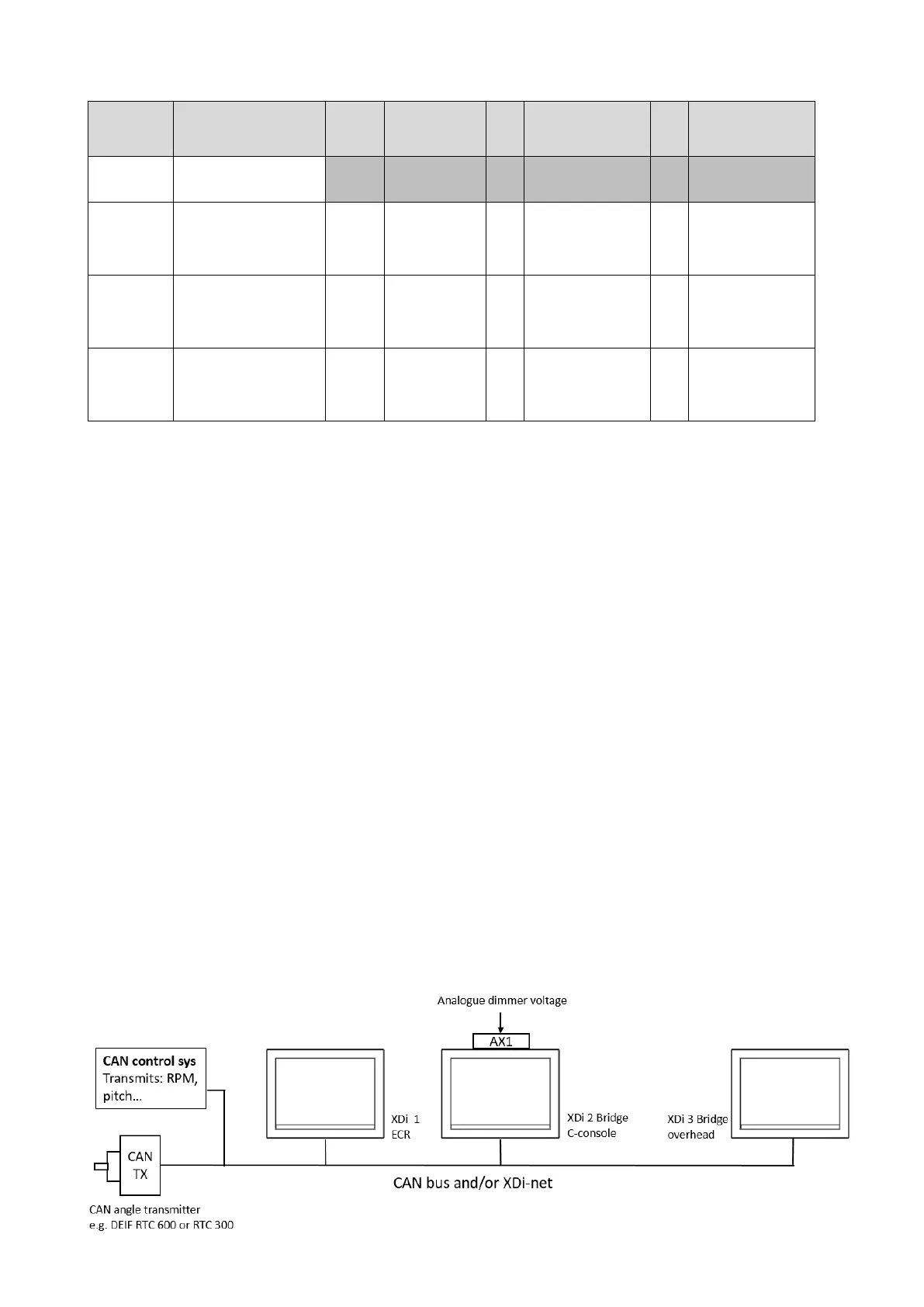
13.7 Application 7 – dimmer control
The dimmer control is independent of the selected virtual indicator, and the dimmer input options are controlled
by the selected product profile. The XDi handles nine dimmer groups via CAN, and the local group that is not
controlled via CAN.

 Loading...
