DESIGNER’S HANDBOOK 4189350049C EN Page 59 of 206
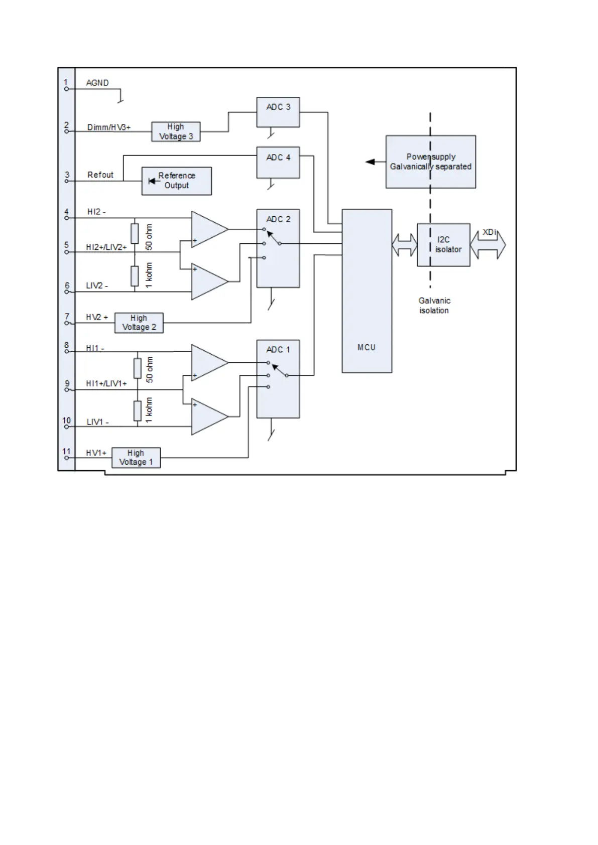
5.6.5 AX1 input circuit - principle diagram
All inputs/outputs on the same AX 1 module are galvanic separated from the XDi’s supply voltage inputs, from both
CAN ports and from input/outputs on other extension modules (XDi 144 and XDi 192 only).
The 2 current inputs (including the low voltage inputs) are differential inputs, but not galvanic separated, so
common mode rejection must be taken into consideration.
The 3 high voltage inputs refer to the same common terminal (AGND).
5.6.6 Input protection
AX1 inputs are protected for over-voltage, and the HI (+/- 20 mA) inputs are over-current protected.
The AX 1 module is protected against accidental connection of 24 V supply voltage between any combinations of
terminals.

 Loading...
