EasyManuals Logo
Home>Deif>Measuring Instruments>XDi Series

Deif XDi Series User Manual

Deif XDi Series
206 pages
To Next Page IconTo Next Page
To Previous Page IconTo Previous Page
Page #36 background imageLoading...
Page #36 background image
DESIGNER’S HANDBOOK 4189350049C EN Page 36 of 206
4.5 XDi power supply and CAN connections
XDi base unit connectors
Type
Terminal
no.
Signal
Marking
Remark
Connector 1
1
CAN 1
connection
CAN 1 GND
Common, should not be connected *)
2
CAN 1 LOW
3
CAN 1 HIGH
4
Supply
Voltage
+24 V DC
Standard power input
5
0V
Dill switch 1
-
ON/OFF
CAN 1 Term
120 termination
Dill switch 2
-
ON/OFF
CAN 2 Term
120 termination
Connector 2
6
CAN 2
connection
CAN 2 GND
Common, should not be connected *)
7
CAN 2 LOW
8
CAN 2 HIGH
9
Supply
Voltage
+24 V DC
Redundant power input
10
0 V
*) The common wire should only be used if an extra dedicated “common” wire is available in the CAN bus cable.
This terminal may not be connected to cable shield or ground!
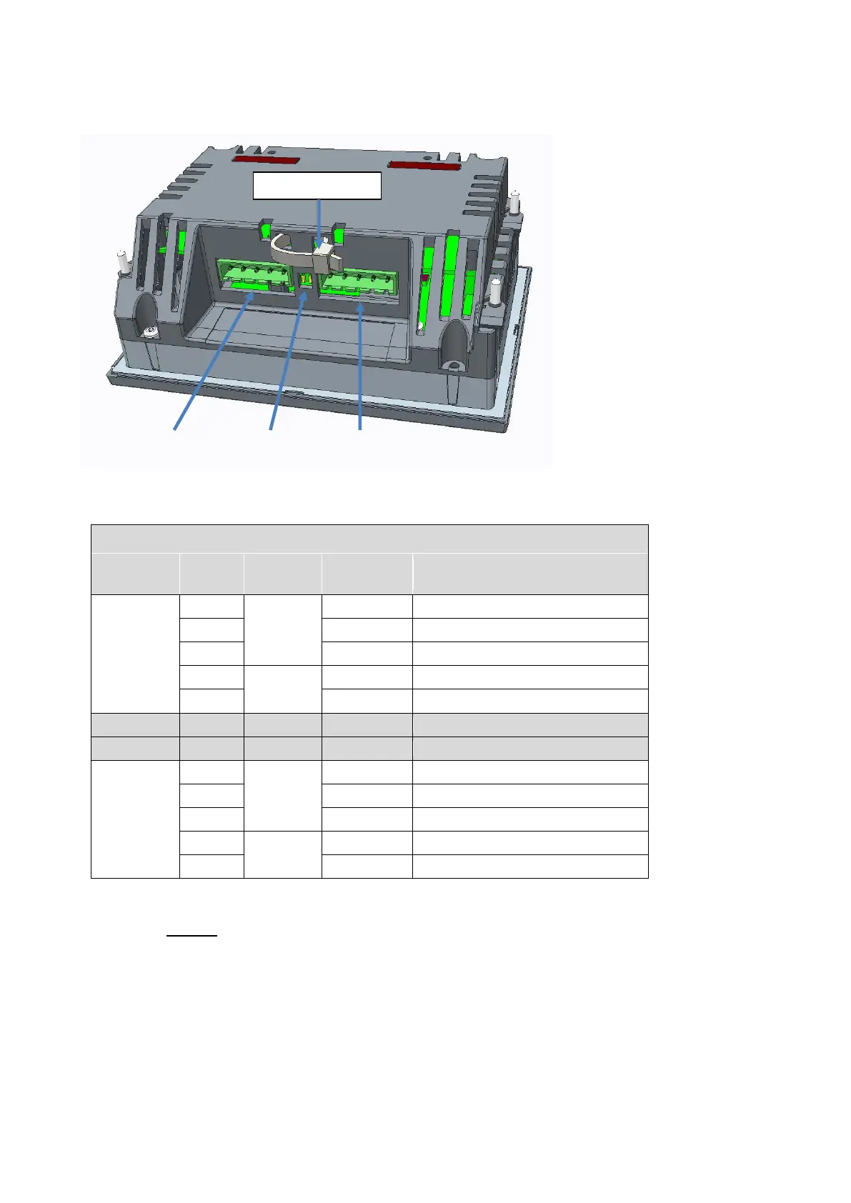
4.5.1 Strain relief of cable and termination of cable shield
When the cable and connectors are mounted on the XDi, the cable should be relieved using a cable strip that can
easily be inserted in the small slots (see drawing).
Connector 2 Termination Connector 1
Cable relief strip

Table of Contents

Questions and Answers:

Question and Answer IconNeed help?

Do you have a question about the Deif XDi Series and is the answer not in the manual?

Deif XDi Series Specifications

General IconGeneral
BrandDeif
ModelXDi Series
CategoryMeasuring Instruments
LanguageEnglish

Related product manuals