DESIGNER’S HANDBOOK 4189350049C EN Page 64 of 206
5.6.8 Connecting to the AX1 module
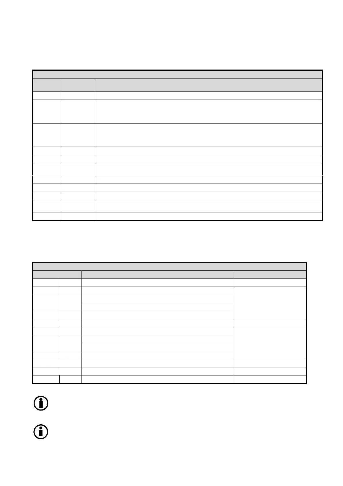
Analogue Extension Module AX1
Analogue common connection (or ground)
Dimmer input configurable in the range, max. 30 V DC, port 3
It can be configured as an extra high voltage indicator input (max. +/-30 V DC), if it is
not used for dimmer.
REF out typ. 7.3 V DC (min. 7 V…max 7.5 V) and max. 10 mA.
This port can also be used as reference potentiometer input, if the external voltage
applied is between 7.5 V and 30 V DC.
Negative input for: High current input (max. +/- 20 mA DC), port 2
Positive input for: Low voltage, low current or high current, port 2
Negative input for: Low voltage (max. +/-2 V DC) or Low current (+/- 2 mA DC), port 2
Positive input for: High voltage (+/-30 V DC), port 1
Negative input for: High current input (max. +/- 20 mA DC), port 1
Positive input for: Low voltage, low current or high current, port 1
Negative input for: Low voltage (max. +/-2 V DC) or Low current (+/- 2 mA DC), port 1
Positive input for: High voltage (+/-30 V DC), port 1
The input wiring to the AX1 module must be in accordance with this table:
Voltage and current connection
High voltage (HV1) input range, max. +/-30 V
Low voltage (LIV1) input range, max. +/- 2 V
Low current (LIV1) input range, max. +/- 2 mA
High current (HI1) input range, max. +/- 20 mA
Hi voltage (HV2) input range, max. +/-30 V
Low voltage (LIV2) input range, max. +/- 2 V
Low current (LIV2) input range, max. +/- 2 mA
High current (HI2) input range, max. +/- 20 mA
Dimmer input/high voltage 3 (DIM/HV3), max. +/-30 V
Terminal 1, analogue common (AGND), is used as the common connection for input REF,
HV1+, HV2+ and DIM/HV3+ .
IMPORTANT: Only one input signal (voltage or current) must be connected to an input port,
so be careful not to connect 2 different sets of input wires to the same input port!

 Loading...
