DESIGNER’S HANDBOOK 4189350049C EN Page 205 of 206
13.8 Application 8 – group dimmer control
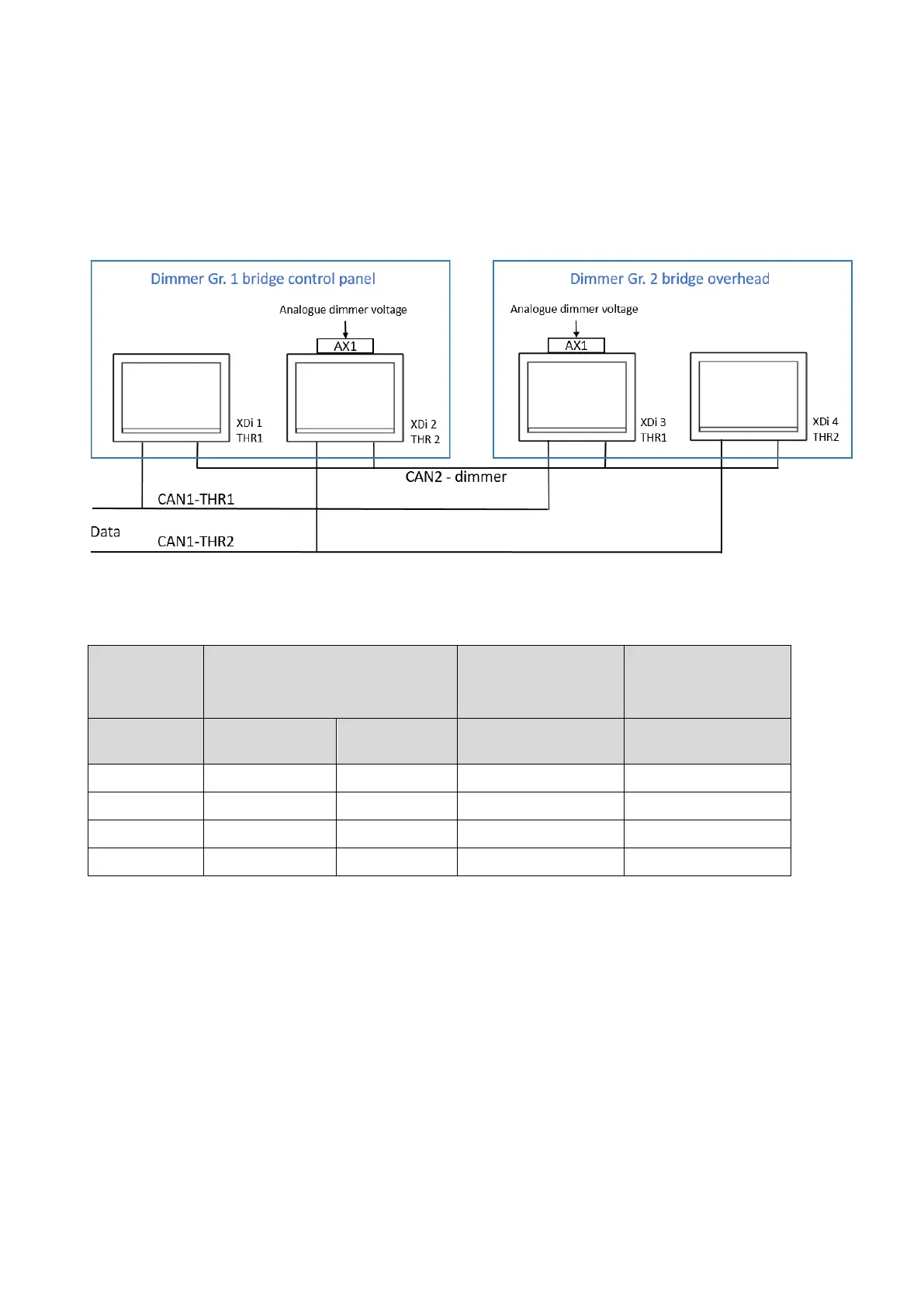
The system in this application note consists of two azimuth thrusters, each with an XDi indicator located in the
control panel and one in the overhead console. CAN data is distributed on two separate CAN lines, both use CAN
input 1 on the XDi.
One XDi in the console and one in the overhead panel are equipped with an AX1 module for dimmer input. Dimmer
level data is shared on CAN 2.
By using the dimmer grouping function, it is possible to individually control the dimmer level of XDi units in the
bridge control panel (gr.1) and XDi units in the bridge overhead panel (gr. 2) on the same CAN bus.
*) The DEIF standard libraries are by default set up to share analogue dimmer data on CAN 1 and CAN 2. As long
as dimmer groups are used, it is not necessary to change to CAN 2.
In this example, however, it may be more practical only to connect CAN 2 on the two XDi units in the bridge
console and similarly only CAN 2 on the two XDi units in the overhead bridge console. If the default dimmer group
1 is used in both locations, it is important to change the default setting of data sharing on the XDi-net, so that
analogue dimmer data is only shared on CAN 2, since the indicators are also interconnected on CAN 1.
Fault symptom: If dimmer data is shared on both CAN 1 and CAN 2, and all XDi units are in group 1, then the
backlight level will jump between the two dimmer levels and make the backlight flicker.

 Loading...
