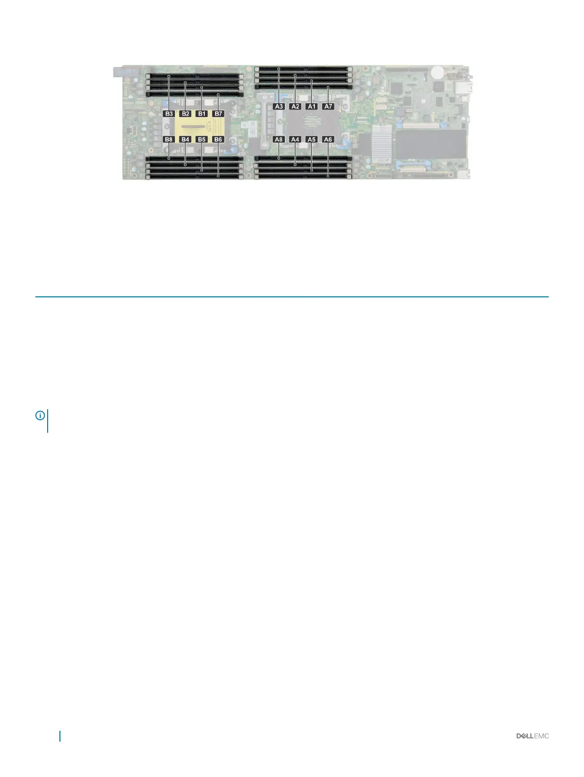
Figure 20. Memory socket locations
Memory channels are organized as follows:
Table 31. Memory channels
Proces
sor
Channel 0 Channel 1 Channel 2 Channel 3 Channel 4 Channel 5
Proces
sor 1
Slots A1 and A7 Slots A2 Slots A3 Slots A8 and A4 Slots A5 Slots A6
Proces
sor 2
Slots B1 and B7 Slots B2 Slots B3 Slots B8 and B4 Slots B5 Slots B6
General memory module installation guidelines
NOTE
: Memory congurations that fail to observe these guidelines can prevent your system from booting, stop responding
during memory conguration, or operating with reduced memory.
The system supports Flexible Memory Conguration, enabling the system to be congured and run in any valid chipset architectural
conguration. The following are the recommended guidelines for installing memory modules:
• RDIMMs and LRDIMMs must not be mixed.
• x4 and x8 DRAM based memory modules can be mixed. For more information, see the Mode-specic guidelines section.
• Up to two RDIMMs can be populated per channel regardless of rank count.
• Up to two LRDIMMs can be populated per channel regardless of rank count.
• If memory modules with dierent speeds are installed, they will operate at the speed of the slowest installed memory module(s) or
slower depending on the system DIMM conguration.
• Populate memory module sockets only if a processor is installed. For single-processor systems, sockets A1 to A8are available. For dual-
processor systems, sockets A1 to A8 and sockets B1 to B8 are available.
• Populate all the sockets with white release tabs rst, followed by the sockets with black release tabs.
• When mixing memory modules with dierent capacities, populate the sockets with memory modules with highest capacity rst. For
example, if you want to mix 8 GB and 16 GB memory modules, populate 16 GB memory modules in the sockets with white release tabs
and 8 GB memory modules in the sockets with black release tabs.
• In a dual-processor conguration, the memory conguration for each processor should be identical. For example, if you populate socket
A1 for processor 1, then populate socket B1 for processor 2, and so on.
• Memory modules of dierent capacities can be mixed provided other memory population rules are followed (for example, 8 GB and 16
GB memory modules can be mixed).
• Mixing of more than two memory module capacities in a system is not supported.
• Populate six memory modules per processor (one DIMM per channel) at a time to maximize performance.
72
Installing and removing system components

 Loading...