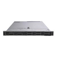
NOTE: Ensure that the processor and the bracket are placed in the tray after you remove the heat sink.
Figure 35. Removing the processor bracket
Next step
Install the non-fabric processor into the processor and heat sink module.
Related link
Removing a sled
Removing the air shroud
Removing a processor and heat sink module
Installing the non-fabric processor into a processor and heat sink module
Installing the non-fabric processor into a processor and heat
sink module
Prerequisite
NOTE
: In a sled which has been congured with mixed CPUs – a fabric processor installed in the CPU2 socket and a non-fabric
processor installed in the CPU1 socket, you must connect the external Omnipath link cables to Port 2 on the OCP carrier card.
Follow the safety guidelines listed in Safety instructions.
Steps
1 Place the processor in the processor tray.
NOTE
: Ensure that the pin 1 indicator on the processor tray is aligned with the pin 1 indicator on the processor.
2 Flex the outer edges of the bracket around the processor ensuring that the processor is locked into the clips on the bracket.
NOTE
: Ensure that the pin 1 indicator on the bracket is aligned with the pin 1 indicator on the processor before placing
the bracket on the processor.
NOTE: Ensure that the processor and the bracket are placed in the tray before you install the heat sink.
88 Installing and removing system components

 Loading...